Multimedia emergency services

a multi-media, emergency service technology, applied in the field of multi-media emergency services, can solve the problems of many monitoring devices not being active, many users may not be physically capable of adequately describing the user's vicinity, and many users may not be able to adequately describe the user's vicinity, etc., to achieve a better picture of the emergency and its impact, and better monitoring of the user's vicinity

Inactive Publication Date: 2006-03-30
AT&T INTPROP I LP
View PDF18 Cites 25 Cited by
  • Summary
  • Abstract
  • Description
  • Claims
  • Application Information

AI Technical Summary

Benefits of technology

[0016] The remote activation of the monitoring devices and the remote reception of the monitored information sent by the monitoring devices enable emergency service personnel to plan an appropriate response to the emergency at hand. Such an arrangement allows for better monitoring of the user's vicinity in an emergency situation without the need for prolonged user participation in narrating or describing the emergency situation. Further, an emergency service provider may obtain a better picture of the emergency and its impact by controlling appropriate monitoring devices available in the user's vicinity. The remote monitoring of the user's vicinity at the time of emergency is also useful to expeditiously gauge the severity of the emergency, and, hence, to prepare an adequate response to help the user in need of emergency assistance.

Problems solved by technology

However, it is easily observed that the user 12 may not always be able to adequately describe the user's vicinity during the emergency.
The user may not even be physically capable of narrating the user's vicinity, for example, when the user suffers a heart attack and wishes just to inform the emergency service provider (e.g., the police or the hospital) of the user's condition without further discussion or details.
However, many monitoring devices may not be already active at the time of emergency, and must be activated by the user or someone else before any condition in the user's vicinity can be monitored.
Furthermore, in many emergency situations (e.g., under threat of physical safety or under an onset of a life-threatening emergency), the user may not be physically capable of accessing the monitoring device to activate it, even if the user wishes to do so.
This may not be desirable, especially when the caller's situation demands prompt and instant attention.

Method used


Image

  • Multimedia emergency services
  • Multimedia emergency services
  • Multimedia emergency services

Examples


Embodiment Construction

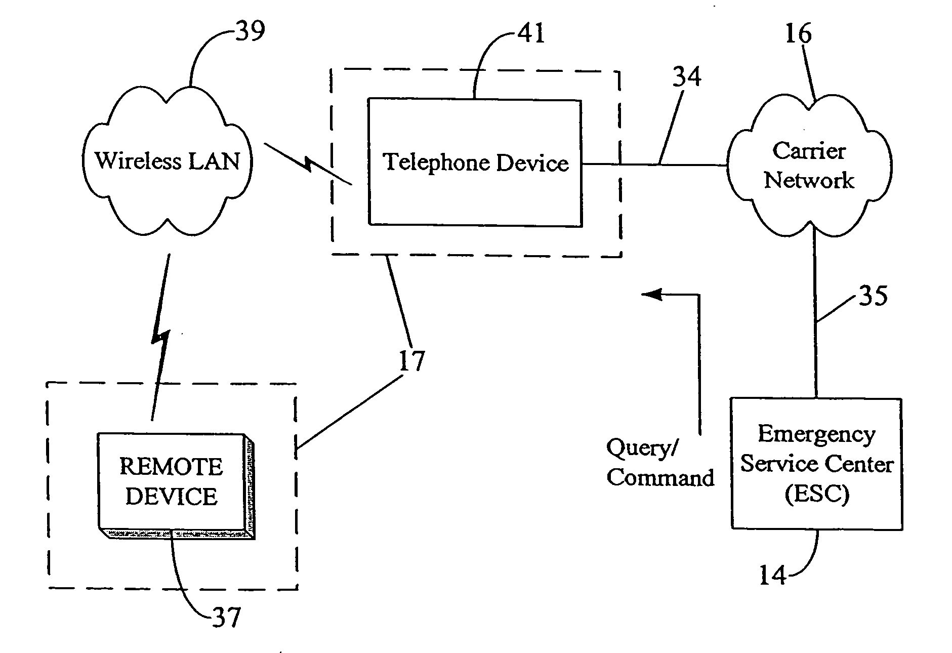
[0024] It is noted at the outset that the numeral 17 is primarily used hereinbelow to indicate that portion of the user's actual household or dwelling which is to be monitored when an emergency is reported, i.e., that portion of the user's household which comprises the relevant vicinity for the user in the time of emergency. Thus, in some situations (e.g., when the user 12 is having a heart attack), the term “household” (as represented by numeral 17) may simply refer to a single room or office within the user's actual household. On the other hand, in some other situations (e.g., when the user's household is robbed or burglarized), numeral 17 may represent the user's entire household, including different rooms, offices, basement, etc., because of the need to monitor different locations, for example, to assess damage or to locate any culprit hiding within the household. Furthermore, the user 12 may not even be physically present in the user's household 17 that is to be monitored. For ...


PUM


Abstract

A system and method for remotely controlling one or more monitoring devices in a user's household in the event of emergency so as to more productively monitor the emergency situation on a real-time basis. The monitoring devices may include a number of multimedia instruments such as a telephone with an answering machine, a computer with a built-in digital camera, a video recording device, a cellular phone with an integrated digital camera, etc. An emergency service provider may remotely activate the monitoring devices in the user's vicinity upon receiving an emergency help request from the user, and receive the information sent by the monitoring devices to enable the service personnel to plan appropriate response to the emergency at hand. Such an arrangement allows for better monitoring of the user's vicinity in an emergency situation without the need for prolonged user participation in narrating or describing the emergency situation. Further, the emergency service provider may obtain a better picture of the emergency and its impact by controlling appropriate monitoring devices available in the user's vicinity. The remote activation and control of a monitoring device may be accomplished via the Internet.

Description

CROSS REFERENCE TO RELATED APPLICATIONS [0001] This application is a continuation of co-pending U.S. patent application Ser. No. 10 / 833,804, the entire contents of which are incorporated herein by reference, which is a continuation of Ser. No. 10 / 402,517, filed Mar. 28, 2003, now U.S. Pat. No. 6,748,052 the entire contents of which are incorporated herein by reference, which is a continuation of U.S. patent application Ser. No. 09 / 740,374, filed Dec. 19, 2000, now U.S. Pat. No. 6,567,502, the entire contents of which are incorporated herein by reference.BACKGROUND OF THE INVENTION [0002] 1. Field of the Invention [0003] The present invention broadly relates to providing emergency services (e.g., the police services) to the public, and more particularly, to a system and method of providing emergency services wherein the emergency service provider (e.g., the police) gets control of one or more monitoring devices in the vicinity of a user requesting emergency help. [0004] 2. Descriptio...

Claims


Application Information

Patent Timeline
Patent Type & Authority Applications(United States)
IPC IPC(8): H04M11/04G08B25/08H04W4/90H04L29/06H04L29/08H04Q9/00
CPCG08B25/08H04W4/22H04L29/06H04L29/06027H04L41/12H04L43/00H04M7/1205H04M11/002H04M11/007H04M11/04H04M2242/04H04Q9/00H04L65/1069H04L67/12H04L69/329Y04S40/164Y04S40/168H04Q2209/43H04L12/2602Y04S40/18H04W4/90Y04S40/00H04L9/40H04L65/1101
Inventor ZELLNER, SAMUEL N.ENZMANN, MARK J.MOTON, ROBERT T. JR.
Owner AT&T INTPROP I LP
Why Eureka
Try Eureka