
Method and arrangement for determining the dispersion of an optical transmission link

a technology of optical transmission link and dispersion, which is applied in the direction of optical apparatus testing, transmission monitoring, instruments, etc., can solve the problems of limited range and capacity of optical transmission system for long-range communication technology

Inactive Publication Date: 2006-03-30
NOKIA SIEMENS NETWORKS GMBH & CO KG
View PDF7 Cites 7 Cited by
  • Summary
  • Abstract
  • Description
  • Claims
  • Application Information

AI Technical Summary

Benefits of technology

[0013] A further advantage of the invention is that, in the case of point-to-point connections, only one modulation unit is required for all wavelengths on the sending side. The same applies to PXCs (optical cross-connects or photonic cross-connects) for each celestial direction.
[0014] The method offers the further advantage that, on the receiving side, it is only necessary to read out the error rate or the number of errors which were corrected by Forward Error Correction (FEC). Other statements about the signal quality are established by utilizing eye pattern and histogram methods, for example.
[0015] A further advantage of the invention is that a measurement run for all active wavelengths provides the residual dispersion.
[0016] The invention has the further advantage that, without using additional components such as a network analyzer and a power measuring unit, it is also possible to measure the non-linear phase (formula 3, P. 8) of an optical transmission link, thereby allowing inferences in relation to the quality of the data transmission. Using the non-linear phase, it is then possible to specify, for example, how many regenerator-free link sections can be integrated into the system and how far the power level can be varied towards higher values before the transmission degrades again due to non-linearities.
[0017] Further advantages of the invention are that no additional data signal errors occur when using an error-correcting code, the data signal information is not compromised by the measuring, and the signal quality is simultaneously checked in parallel with the measured variable.
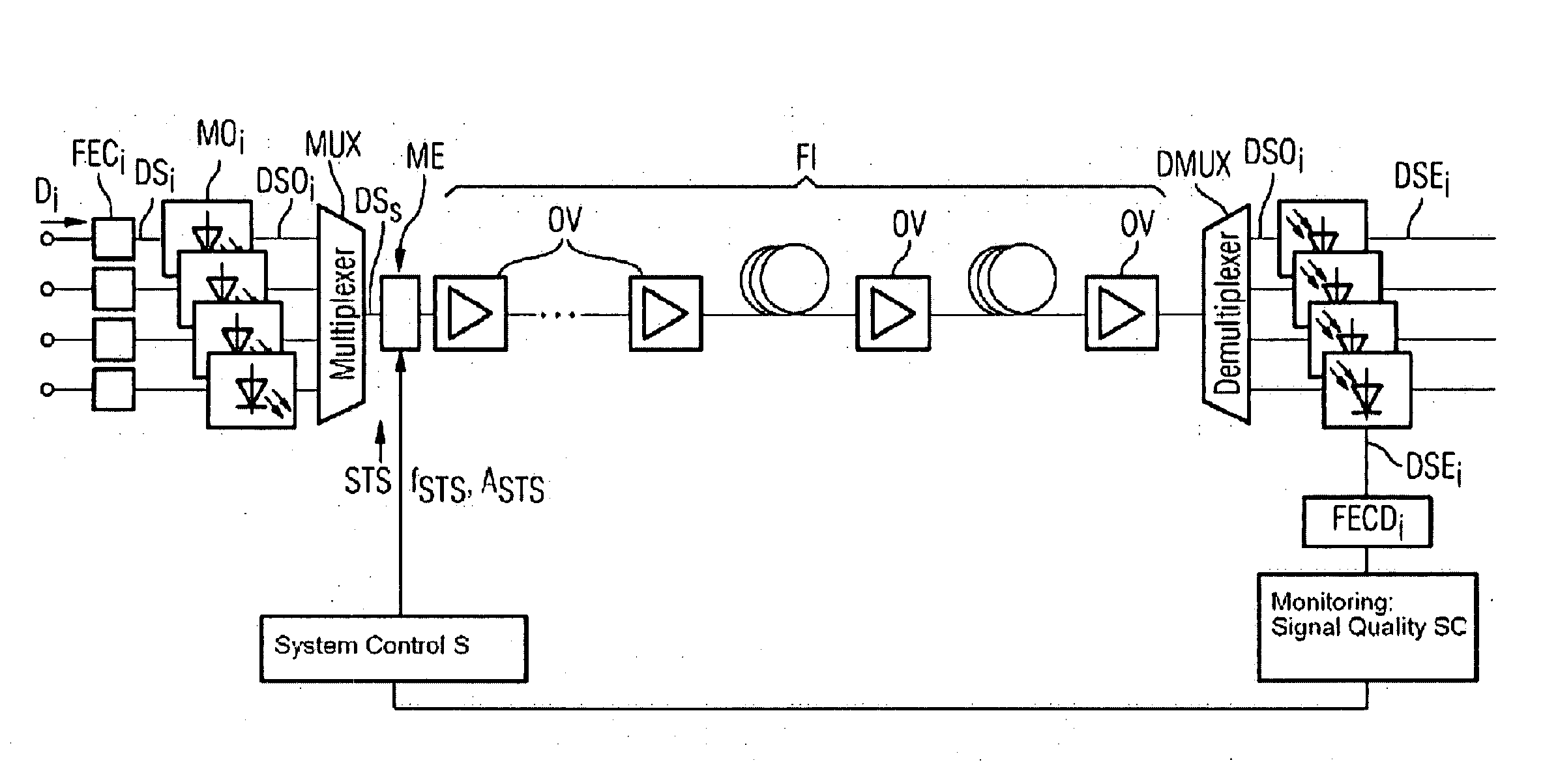
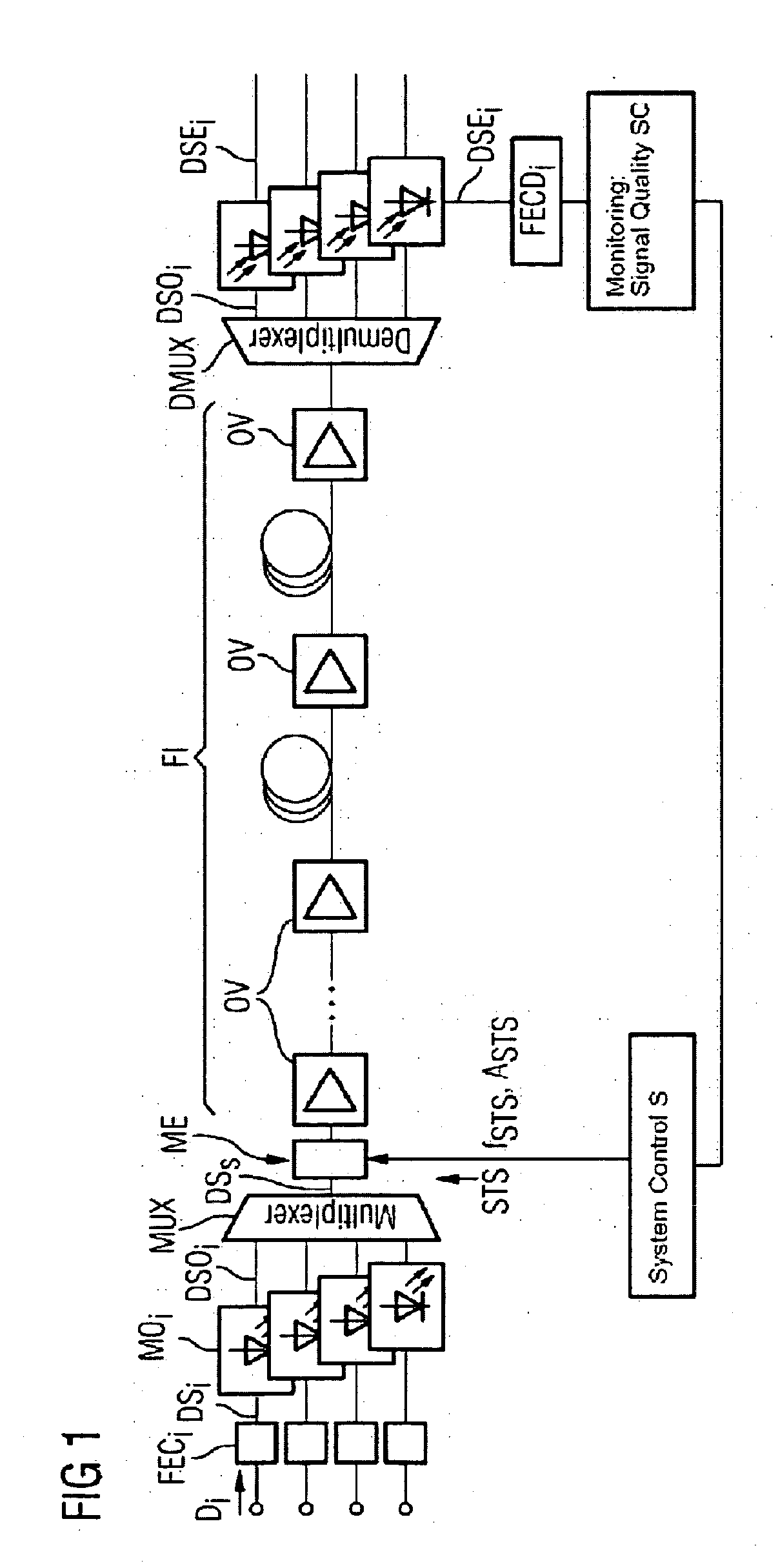
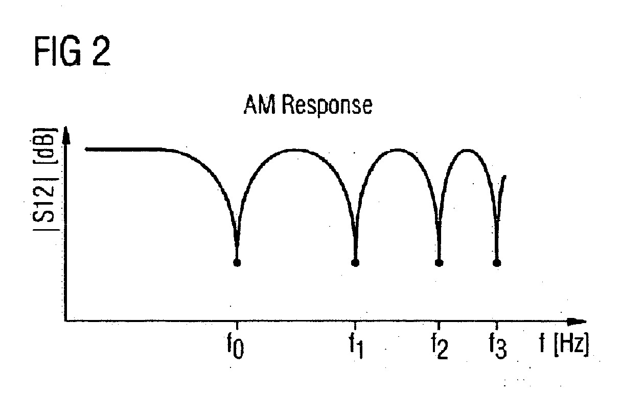
[0018] The invention will now be explained with reference to an exemplary embodiment and with reference to FIGS. 1 and 2.

Problems solved by technology

The range and capacity of optical transmission systems for long-range communications technology are limited inter alia by signal distortions which are caused by the dispersion in the transmission fiber.

Method used


Image

  • Method and arrangement for determining the dispersion of an optical transmission link
  • Method and arrangement for determining the dispersion of an optical transmission link
  • Method and arrangement for determining the dispersion of an optical transmission link

Examples


Embodiment Construction

[0021] In an optical transmission link such as that which is illustrated schematically in FIG. 1, the data signals Di to be transmitted are initially protected in an FEC encoder FECi. A plurality of optical carrier signals are then modulated with the encoded data signals DSi in modulators MOi, and the optical data signals DSOi are combined by the multiplexer MUX to form a multiplex signal DSs on the sending side. In the modulation unit ME, a sinusoidal noise signal STS is modulated (preferably amplitude-modulated) onto all of the optical data signals DSs together, said optical signals being output by the multiplexer MUX. The term modulation here is intended also to include equally acting effects that are caused by superimposition. Consequently, the signal quality is degraded and the number of bit errors which must be corrected by the FEC is increased. The noise signal STS can be varied in both frequency fSTS and in amplitude ASTS. Both modulation parameters are set by means of a sys...


PUM


Abstract

The invention relates to a method and an arrangement for determining the dispersion of an optical transmission link. By determining the signal quality, the bit error rate is measured for a modulated data signal depending on the modulation frequency of a noise signal (STS). The dispersion coefficient of the transmission link is calculated on the basis of the resulting discrete minima of the bit error rates. These measurements can take place advantageously during the operation of the data transmission. The method also provides additional information about the quality of the data transmission by determining the non-linear phase shift.

Description

CROSS REFERENCE TO RELATED APPLICATIONS [0001] This application claims priority to the German application No. 10 2004 047 021.9, filed Sep. 28, 2004 and which is incorporated by reference herein in its entirety. FIELD OF INVENTION [0002] The invention relates to a method and an arrangement for determining the dispersion of an optical transmission link. SUMMARY OF THE INVENTION [0003] The range and capacity of optical transmission systems for long-range communications technology are limited inter alia by signal distortions which are caused by the dispersion in the transmission fiber. The standard single-mode fibers (SSMF) that are often used have a dispersion coefficient of approximately 17 ps / (nm*km) in the wavelength window of 1550 nm. With channel data rates of 2.5 Gbit / s, it is possible to implement dispersion-limited regenerator intervals of approximately 1000 km without compensating measures. Since the range decrease is inversely proportional to the square of the channel data r...

Claims


Application Information

Patent Timeline
Patent Type & Authority Applications(United States)
IPC IPC(8): H04B10/08
CPCG01M11/338G01M11/335
Inventor GOTTWALD, ERICH
Owner NOKIA SIEMENS NETWORKS GMBH & CO KG
Learn More