
System and method for sealing high intensity discharge lamps

a technology of high-intensity discharge and sealing cracks, which is applied in the field of lighting systems, can solve the problems of residual potential stresses and sealing cracks, and various stresses due to the sealing process

Inactive Publication Date: 2006-03-30
GENERAL ELECTRIC CO
View PDF37 Cites 21 Cited by
  • Summary
  • Abstract
  • Description
  • Claims
  • Application Information

AI Technical Summary

Problems solved by technology

In either case, various stresses may arise due to the sealing process, the interface between the joined components, and the materials used for the different components.
For example, the component materials may have different mechanical and physical properties, such as different coefficients of thermal expansion (CTE), which can lead to residual stresses and sealing cracks.
These potential stresses and sealing cracks are particularly problematic for high-pressure lamps.
However, for high temperature lamp applications, these are challenging requirements.
The above approach may be disadvantageous in several respects.
Firstly, the furnace used in the above described technique provides a relatively diffuse heat source with a low temperature gradient.
Hence, the technique does not provide a desired control of seal length and seal microstructure.
Further, the above technique may not be useful for a wide variety of lamp geometries.
The above technique may prove disadvantageous in such applications, as the diffuse heat produced by the furnace may result in undesirable heating of the dosing material during sealing of one end of the lamp.

Method used


Image

  • System and method for sealing high intensity discharge lamps
  • System and method for sealing high intensity discharge lamps
  • System and method for sealing high intensity discharge lamps

Examples


Embodiment Construction

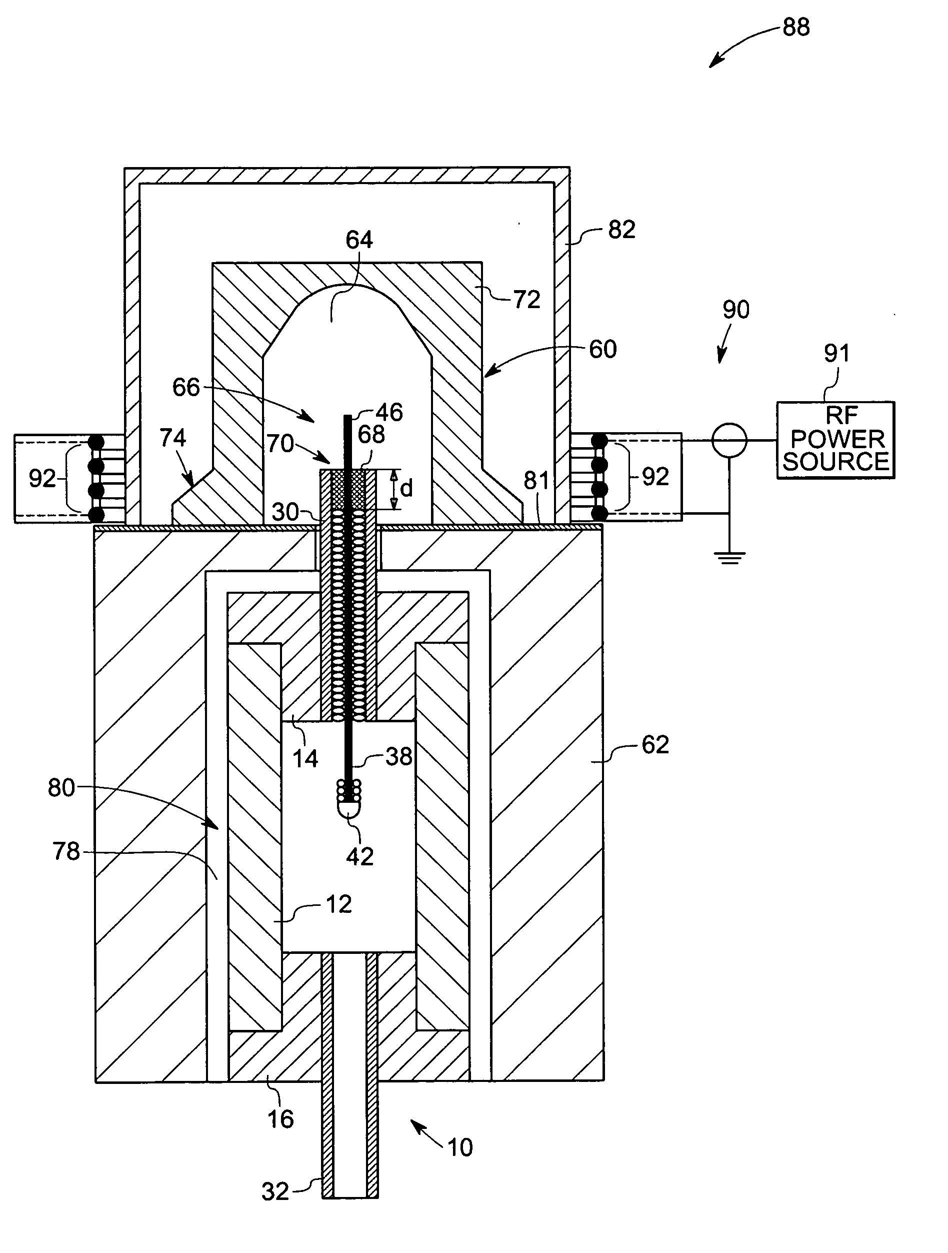
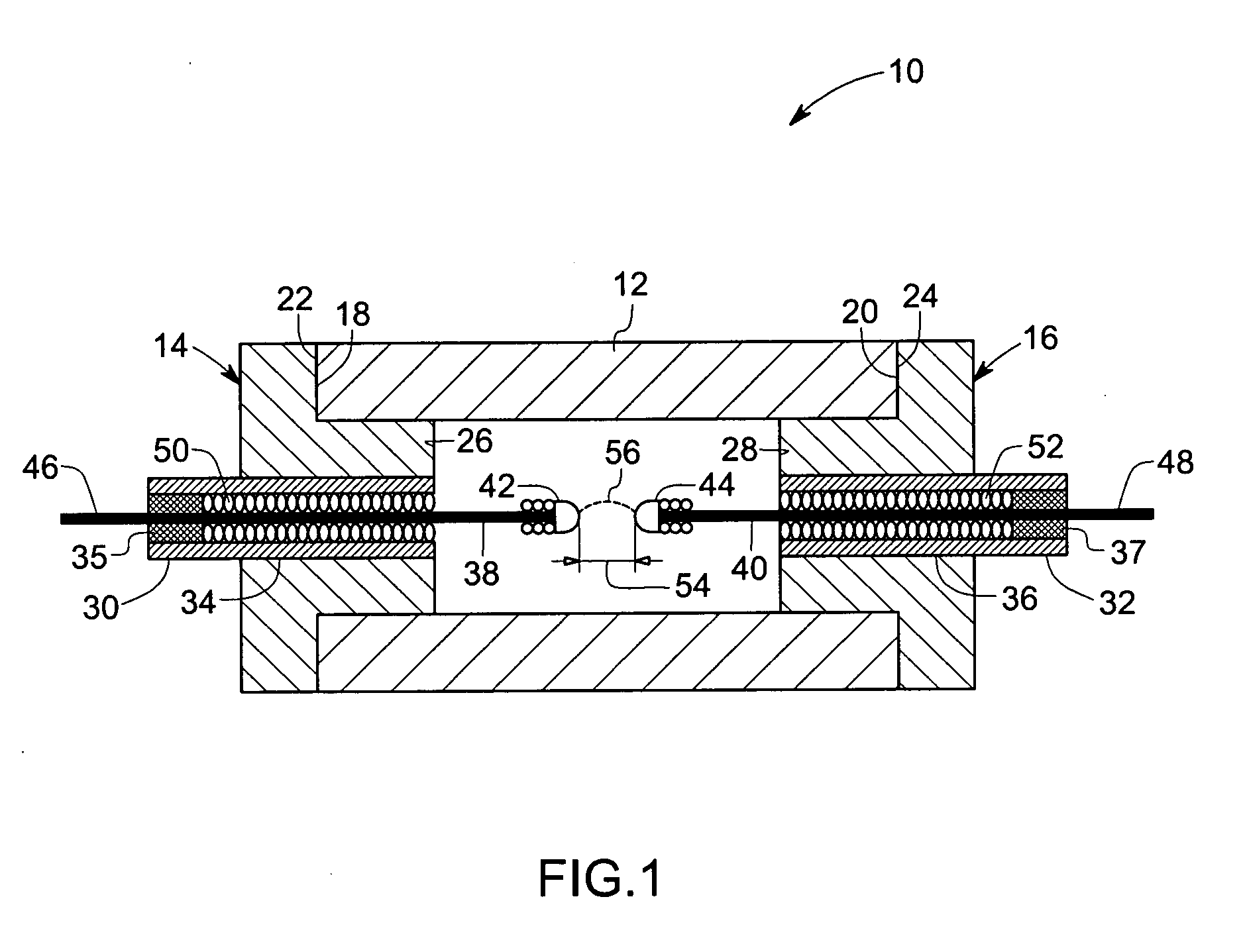
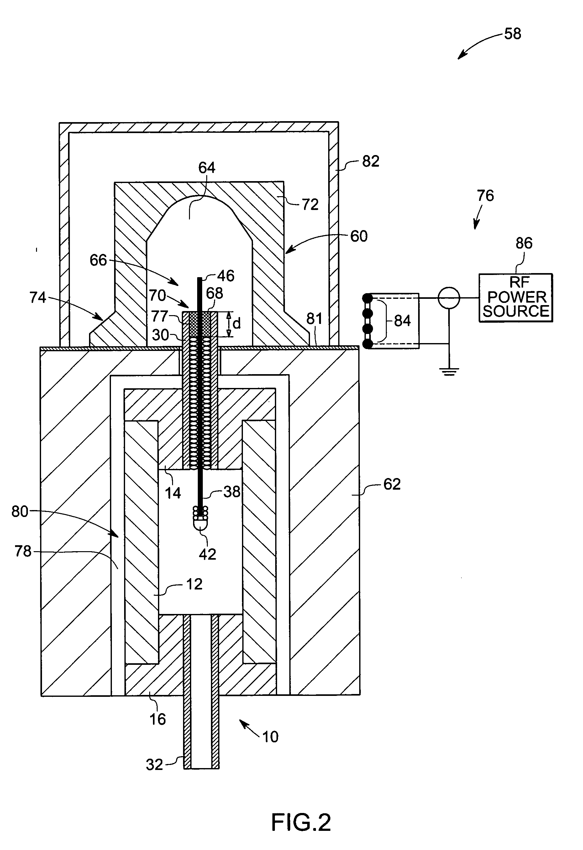
[0028] Aspects of the present technique provide unique sealing systems and methods for sealing between a wide variety of lamp components at high temperatures, for example, by providing localized heating and a high temperature gradient in the sealing region. Localized heating and a high temperature gradient minimize thermal stress in the components being sealed and substantially reduce or prevent cracking during heat-up, sealing, and cool-down stages of the sealing operation. Moreover, localized heating also aids retention of a lamp dose during the sealing operation. A high temperature gradient provides desirable microstructure control for both crystalline and glass phases of the seal. The unique features introduced above are described with respect to several exemplary embodiments of the present technique illustrated hereinafter.

[0029] Turning now to the drawings, FIG. 1 is a cross sectional view of an exemplary lamp 10 wherein aspects of the present technique are applicable. As ill...


PUM


Abstract

In accordance with certain embodiments, the present technique includes a system for sealing a lamp including a thermal shield and a thermally susceptible enclosure disposed adjacent the thermal shield. The thermal shield has a first receptacle adapted to receive a first portion of the lamp. The thermally susceptible enclosure comprises a wall about a second receptacle adapted to receive a second portion of the lamp. The wall has a varying thickness in a desired sealing region between the first and second portions of the lamp.

Description

BACKGROUND [0001] The invention relates generally to the field of lighting systems and, more particularly, to high-intensity discharge (HID) lamps. Specifically, embodiments of the present technique provide improved sealing features for such lamps. [0002] High-intensity discharge lamps are often formed from a tubular body or arc tube that is sealed to one or more end structures. The tubular body may be made of any ceramic material, including polycrystalline alumina (PCA), sapphire, single crystal yttria aluminum garnet (YAG) and polycrystalline YAG. The end structures are often sealed to this ceramic tubular body using a seal glass, which has physical and mechanical properties matching those of the ceramic components and the end structures. Sealing usually involves heating the assembly of the ceramic tubular body, the end structures and the seal glass, to induce melting of the seal glass and a reaction with the ceramic bodies to form a strong chemical and physical bond. The ceramic ...

Claims


Application Information

Patent Timeline
Patent Type & Authority Applications(United States)
IPC IPC(8): H01J9/38H01J9/00H01J9/10H01J9/46
CPCH01J9/266
Inventor BEWLAY, BERNARD PATRICKKNUDSEN, BRUCE ALANBREWER, JAMES ANTHONY
Owner GENERAL ELECTRIC CO
Learn More