Trial disk implant

a technology of disk implant and implant, which is applied in the field of trial disk implant, can solve the problems of affecting the determination of the correct size of the disk implant, the potential misalignment of the implant with the vertebral endplate, and the further complicated surgical procedure, so as to reduce the reliance of personnel on fluoroscopy and minimize exposure to harmful radiation

Inactive Publication Date: 2006-03-30
DEPUY SPINE INC (US)
View PDF99 Cites 338 Cited by
  • Summary
  • Abstract
  • Description
  • Claims
  • Application Information

AI Technical Summary

Benefits of technology

[0009] In another embodiment, the present invention is a method of selecting an artificial intervertebral disk to be inserted between two adjacent vertebral endplates, comprising the steps of inserting between two adjacent vertebral endplates a trial intervertebral disk implant. The disk implant includes a first plate, a second plate, a conformable layer between the first and the second plates, and a pressure sensor within the conformable layer. Further steps include measuring a distribution of compression force exerted by the endplates between which the trial implant has been inserted and comparing the measured distribution of compression force to a distribution that minimizes variation of distribution of compression force while supporting abutting vertebrae in a substantially correct position relative to each other to thereby select an artificial disk.
[0011] The present invention offers a number of advantages. A flexible layer allows extra degrees of freedom when inserted between the adjacent vertebral endplates. Pressure sensors can measure pressure distribution exerted by the endplates. The combination of these features allows the surgeon to design an optimally shaped permanent disk implant. Furthermore, the positional detectors that transmit the information about the location of the trial implant to the surgeon, reduces reliance of the personnel on fluoroscopy or X-rays thus minimizing exposure to harmful radiation.

Problems solved by technology

Distraction of an intervertebral space necessary to create clearance sufficient for insertion of the disk implant results in potential misalignment of the implant with the vertebral endplates.
The surgical procedure can be further complicated by techniques that obstruct the surgeon's field of vision, thereby impeding, in particular, the determination of the correct disk implant size.

Method used


Image

  • Trial disk implant
  • Trial disk implant
  • Trial disk implant

Examples


Embodiment Construction

[0030] The foregoing and other objects, features and advantages of the invention will be apparent from the following more particular description of preferred embodiments of the invention, as illustrated in the accompanying drawings in which like reference characters refer to the same parts throughout the different views. Elements having the same number in different figures represent the same item. The drawings are not necessarily to scale, emphasis instead being placed upon illustrating the principles of the invention.

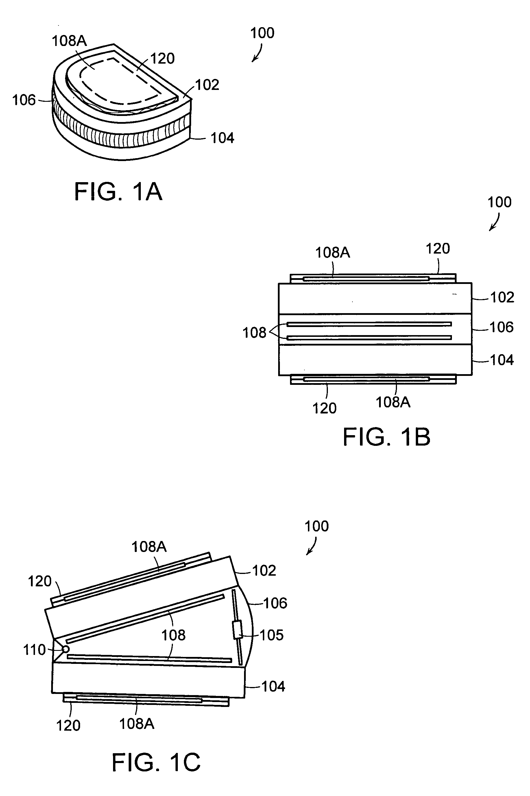
[0031] Referring to FIGS. 1A through 1C, in one embodiment, the present invention is a trial intervertebral disk implant 100 comprising first plate 102, second plate 104 adjacent to first plate 102, conformable layer 106 between first and second plates 102 and 104, and one or more sensors 108 within conformable layer. Sensors 108 can be selected from pressure, angle or distance sensors, e.g. proximity.

[0032] Examples of suitable materials of construction of plates 10...


PUM


Abstract

A trial intervertebral disk implant includes a first plate, a second plate, adjacent to the first plate, a conformable layer between the first and the second plates, and a pressure sensor within the conformable layer. The pressure sensor measures a distribution of compression force exerted by the first and the second plates on the conformable layer. The trial implant includes indicating means for indicating a position of the first and the second plates relative to each other, and locating means, for locating a position of the trial implant relative to the vertebrae between which said trial implant has been placed. The trial implant further includes at least one retractable member, connected to at least one of the first and the second plates. The retractable member can be extended or retracted through an aperture defined by a surface of the plate that is proximal to an abutting vertebra.

Description

BACKGROUND OF THE INVENTION [0001] The human spinal column consists of discrete, sequentially coupled bones (vertebrae) cushioned by cartilaginous spacers, referred to as intervertebral disks, disposed between opposing vertebral endplates. Intervertebral disks are elastic, allowing the spine to retain a high degree of flexibility. Failure of an intervertebral disk usually requires surgical intervention that may include implantation of artificial disks or other devices that restore the height of the spinal column and a natural angle between the adjacent vertebrae. To prepare the intervertebral space for implantation of an artificial disk, the surgeon removes the damaged disk material, distracts the adjacent vertebrae and, once the proper gap between the adjacent vertebrae has been created, inserts an implant. [0002] Distraction of an intervertebral space necessary to create clearance sufficient for insertion of the disk implant results in potential misalignment of the implant with th...

Claims


Application Information

Patent Timeline
Patent Type & Authority Applications(United States)
IPC IPC(8): A61F2/44A61F2/46A61B5/103
CPCA61B5/03A61F2310/00029A61B5/4514A61B2562/02A61F2/442A61F2/4684A61F2002/30069A61F2002/30405A61F2002/30471A61F2002/30523A61F2002/30525A61F2002/30538A61F2002/30556A61F2002/30563A61F2002/30566A61F2002/30579A61F2002/30617A61F2002/30841A61F2002/4658A61F2002/4666A61F2002/4668A61F2220/0025A61F2220/0091A61F2250/0006A61F2250/0009A61F2250/0097A61F2310/00017A61F2310/00023A61B5/0538
Inventor SUTTON, JEFFREY K.O'NEIL, MICHAELDAVIS, KRISTY LYNNSERHAN, HASSAN
Owner DEPUY SPINE INC (US)
Why Eureka
Try Eureka