Methods, systems and computer program products for altering video images to aid an operator of a fastener insertion machine

a technology of video images and fasteners, applied in the field of methods, systems and computer program products for altering video images, can solve the problems of insufficient clearly demonstrated hand drawn illustrations, paper-copy print-outs of computer-generated illustrations, and/or exemplary completed parts, etc., to reduce the chances of operator errors and improve the speed and efficiency of operators

Inactive Publication Date: 2006-03-30
HAEGER
View PDF25 Cites 18 Cited by
  • Summary
  • Abstract
  • Description
  • Claims
  • Application Information

AI Technical Summary

Benefits of technology

[0010] Once the setup for a particular work piece is prepared, the system generates a series of images, or changes to an image, showing each of the steps of the sequence and the particular fastener to be inserted during that step. These images or changes may then be used for setting up the fastener insertion machine(s), and also for training and quality assurance once the fastener insertion machine(s) is set up. In particular, the images / changes assist an operator in knowing which fastener is to be inserted next in sequence, reducing the chances of operator error (i.e., making it less likely than the operator will miss insertion of a fastener, insert the wrong fastener, insert a fastener in the wrong place, etc.). The system should also improve the speed and efficiency of operators inserting fasteners into work pieces. In addition, because a signal is received by the system each time an insertion process is accomplished by the machine, the system is able to track (count) the actual insertions and update the displayed image, allowing the operator to confirm where he / she is with just a glance at the displayed image. This allows the user to stop, take a break, or otherwise be interrupted and then be able to return to work and pick up precisely where he / she left off.

Problems solved by technology

However, in many cases, all of the folds, bends or cuts are made to the work piece before any fasteners are inserted.
Hand drawn illustrations, paper-copy print-outs of computer-rendered illustrations, and / or exemplary completed parts are all often inadequate to clearly demonstrate where and on the work piece and in what sequence each fastener is to be inserted.

Method used


Image

  • Methods, systems and computer program products for altering video images to aid an operator of a fastener insertion machine
  • Methods, systems and computer program products for altering video images to aid an operator of a fastener insertion machine
  • Methods, systems and computer program products for altering video images to aid an operator of a fastener insertion machine

Examples


Embodiment Construction

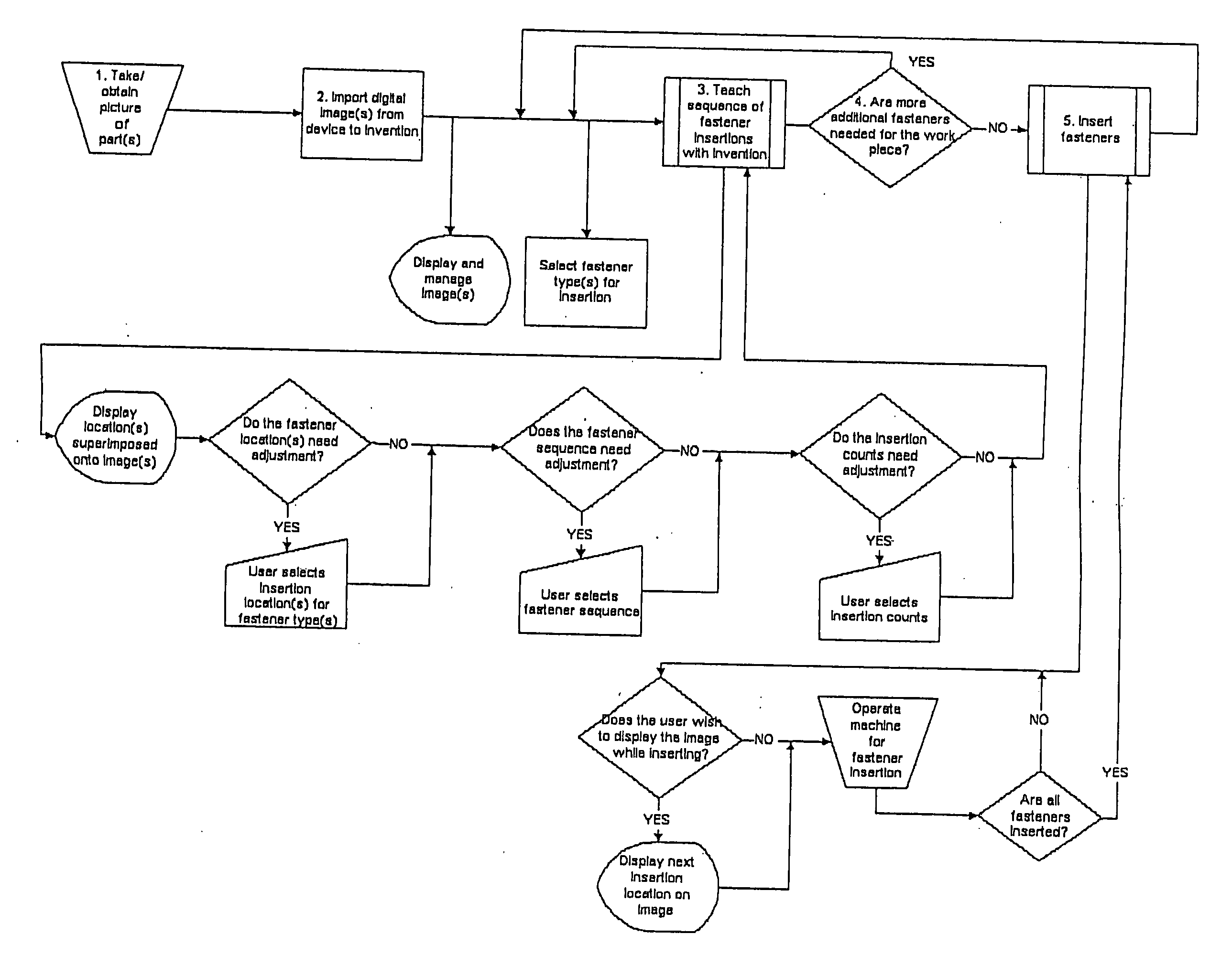
[0020] The system of the present invention includes a computer processor running one or more computer programs, at least one video display, at least one operator input device, and at least one connection to a machine—preferably a fastener insertion machine.

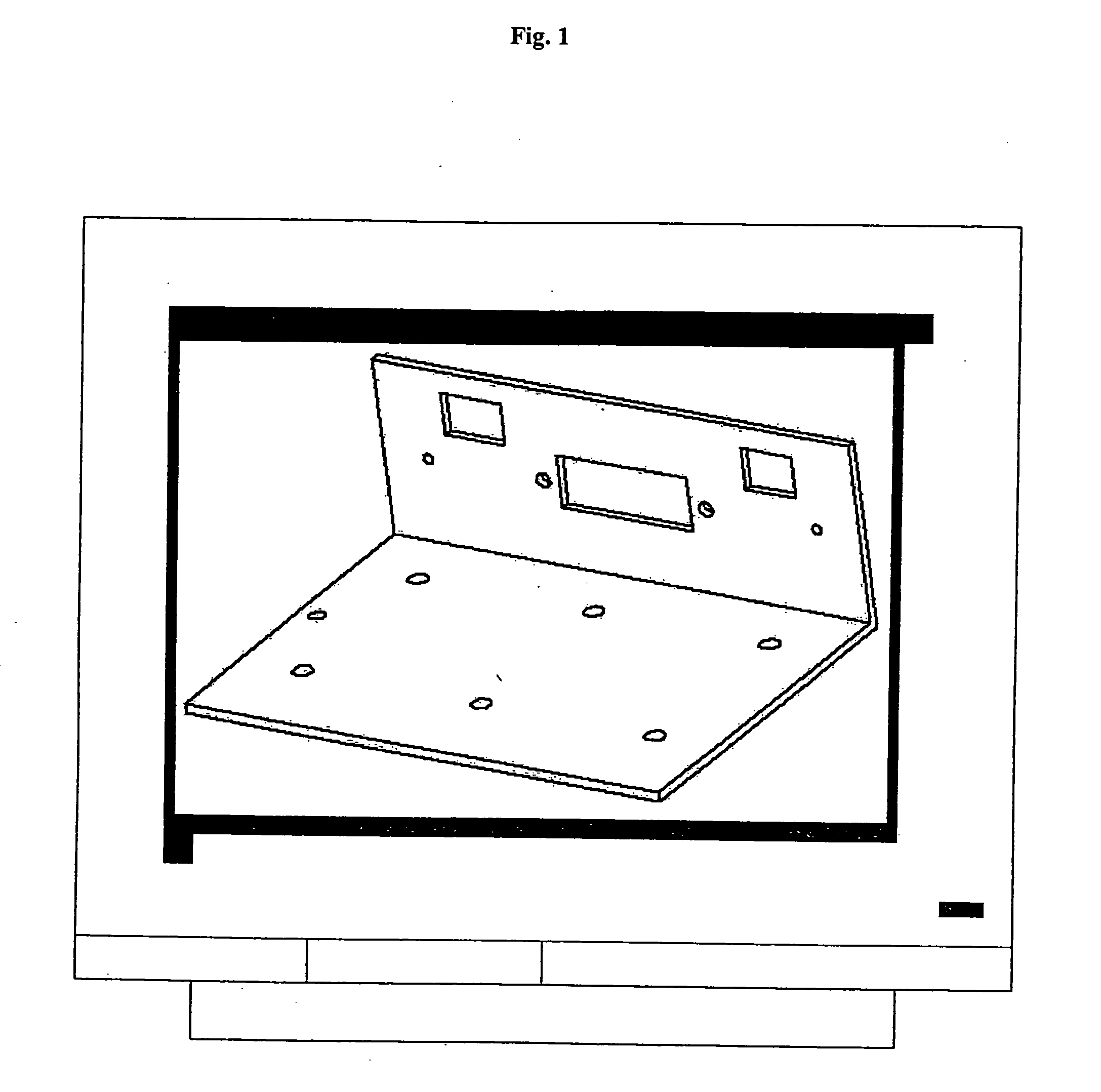
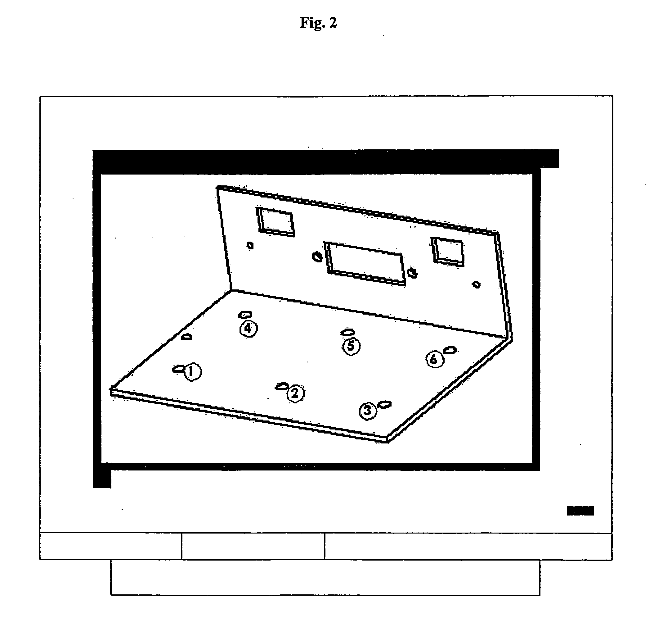
[0021] Referring to the exemplary embodiment illustrated in the drawings, but without limiting the scope of the claims or the scope of potential applications of the present invention, in use, an operator first obtains a computer file containing an image (preferably digital) of a subject work piece by, for example, taking a digital picture of the work piece. This image (file) is imported into the system of the present invention so that it may be displayed on a video screen, as shown in the exemplary work piece displayed in FIG. 1. The system then provides a menu from which the user may select one of many different types of fasteners, with many standard and custom descriptions available to choose from to identify a particular type ...


PUM


Abstract

The present invention provides methods, systems and computer program products for altering video images including superimposing objects onto the images, particularly addressed to identifying fastener insertion locations onto displayed images of a work pieces. The invention is capable of importing an image of a work piece contained in a computer file, displaying the image, and altering the displayed image and/or superimposing objects onto the image to show the location(s), sequence(s) and/or type(s) of fasteners to be inserted onto the displayed work piece according to operator input and instructions. After each insertion is completed, the display is again altered to show the completion. During use, the system is capable of tracking the fastener installations and updating the video display to show the current status of insertions on the work piece.

Description

[0001] This application claims the benefit of U.S. Provisional Application No. 60 / 614,663 filed on Sep. 29, 2004 which is incorporated herein by this reference.BACKGROUND OF THE INVENTION [0002] The present invention relates to methods, systems and computer program products for altering video images including superimposing objects onto video images, and utilizing said objects and images for use in various manufacturing operations with a machine. The invention is particularly directed to methods, systems, and computer program products that are capable of receiving an image (e.g. digital picture file) of a given work piece (such as a metallic automobile door frame), displaying the image on a video screen, establishing object locations on the image of said work piece for different components to be attached, installed, cut, placed or adhered (e.g. manufacturing operations) to the work piece, and use of said objects and images to aid a machine operator in the manufacturing of the work pi...

Claims


Application Information

Patent Timeline
Patent Type & Authority Applications(United States)
IPC IPC(8): G06F19/00
CPCG05B19/406G05B2219/31479G05B2219/31455G05B2219/31046Y02P90/02
Inventor CANNEDY, JEFFBOSTER, T C
Owner HAEGER
Why Eureka
Try Eureka