Remote copy system
a copy system and remote copy technology, applied in the field of remote copy systems, can solve the problems of lowering system operating costs and large volume, and achieve the effect of low cos
- Summary
- Abstract
- Description
- Claims
- Application Information
AI Technical Summary
Benefits of technology
Problems solved by technology
Method used
Image

Examples
first embodiment
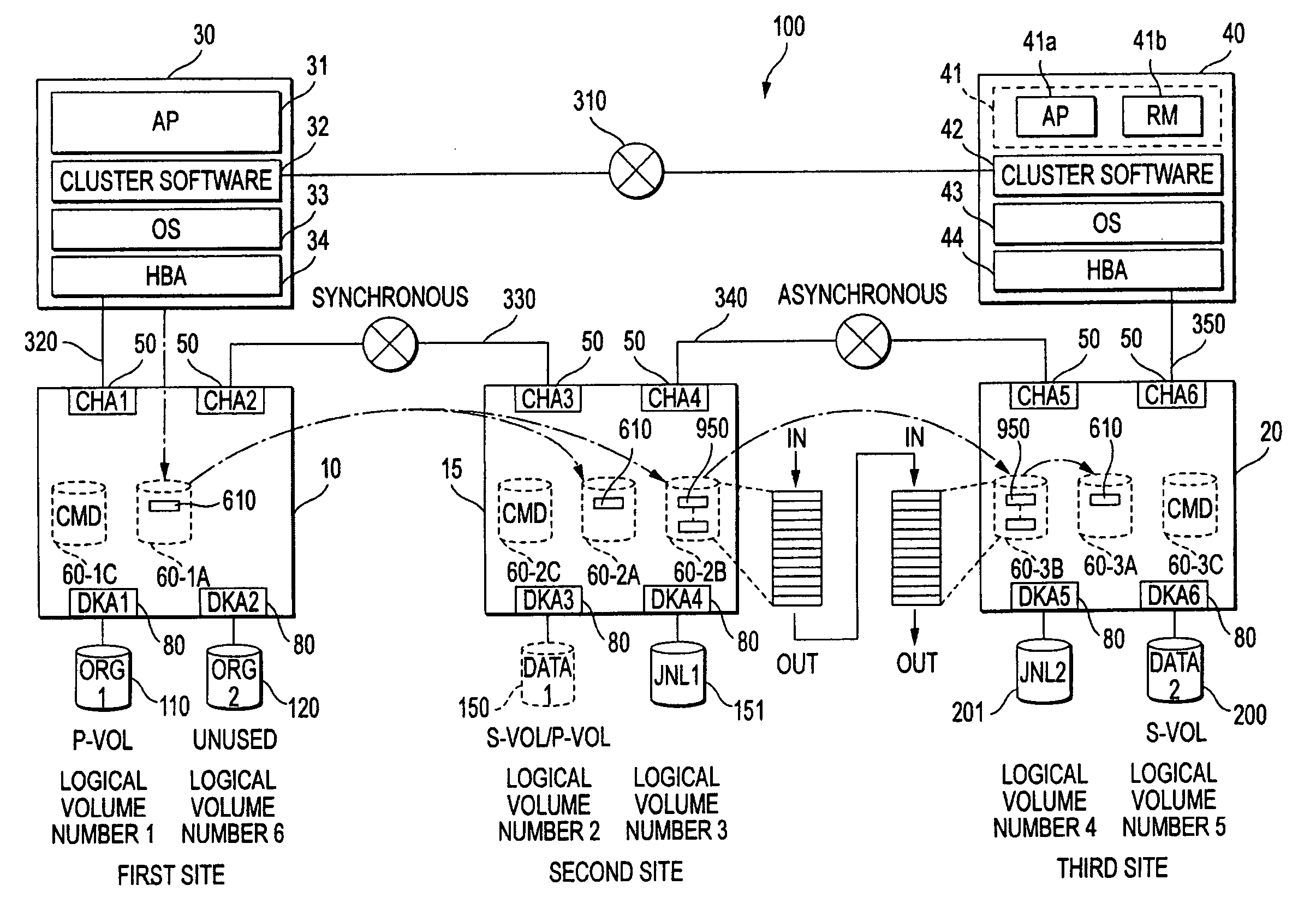
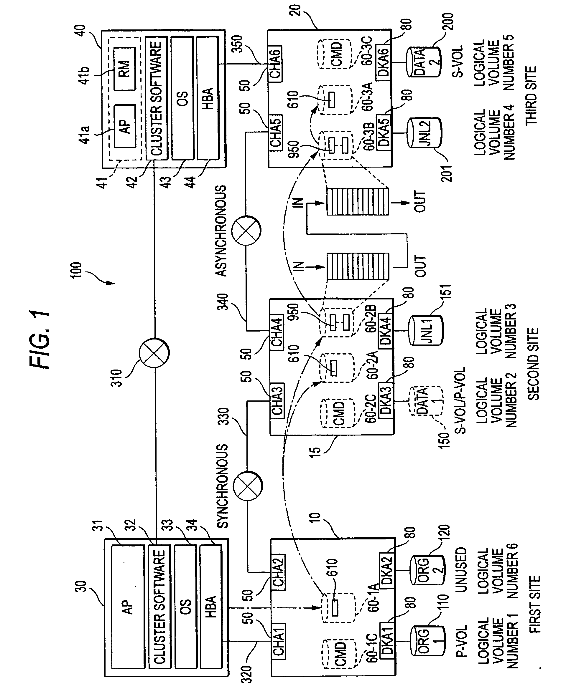
[0045]FIG. 1 is a schematic diagram of a remote copy system 100 according to the present invention. The remote copy system 100 includes a first storage system 10 arranged in a first site (primary site or main site), a second storage system 15 arranged in a second site (secondary site or local site), and a third storage system 20 arranged in a third site (remote site). The second site is located near to the first site while the third site is located far from the first site. The first storage system 10 is connected to a host computer (first upper level computing system) 30 to build an operating (active) data processing system. Further, the third storage system 20 is connected to a host computer (second upper level computing system) 40 to build an alternative (ready) data processing system. These data processing systems comprise clusters. When the operating data processing system is out of order, the data processing systems are configured to perform failover to the alternative data pro...
second embodiment
[0080]FIG. 18 is a schematic diagram showing a remote copy system 102 according to a second embodiment of the present invention. In FIG. 18, the same components as those in FIG. 1 have the same reference numerals, so that the detailed description thereof will be omitted. According to the present embodiment, a logical volume (Data1) 150 is a physical volume having addresses for designating a storage area, provided by the second storage system 15, from the first storage system 10.
[0081]FIG. 19 shows a pair configuration information table 510. In the present embodiment, since the virtual volume is not established, a virtualization ‘ON’ flag is not arranged in the same table.
[0082]FIG. 20 is a flow chart for explaining an initial configuration procedure of the remote copy system 102. Each configuration herein can be set such that the user can perform a desired input operation through a graphic user interface (GUI) of service processor or the host computers 30 and 40. The user register...
third embodiment
[0086]FIG. 23 is a schematic diagram showing a remote copy system 103 according to a third embodiment of the present invention. In FIG. 23, the same components as those in FIG. 1 have the same reference numerals, so that the detailed description thereof will be omitted. In the present embodiment, the operating data processing system (the first storage system 10 or the host computer 30) arranged in the first site and the alternative data processing system (the third storage system 20 or the host computer 40) arranged in the third site are owned by the client, while a second storage system 16 arranged in the second site is owned by a third party. The third party lends the second storage system 16 to the client. The client may be a businessman borrowing the second storage system 16 from the third party, and does not include a general client receiving services from the operating or alternative data processing system. Since each of the storage systems 10, 15, and 20 are very expensive sy...
PUM
 Abstract
Description
Claims
Application Information
 - R&D
- Intellectual Property
- Life Sciences
- Materials
- Tech Scout
- Unparalleled Data Quality
- Higher Quality Content
- 60% Fewer Hallucinations
Browse by: Latest US Patents, China's latest patents, Technical Efficacy Thesaurus, Application Domain, Technology Topic, Popular Technical Reports.
© 2025 PatSnap. All rights reserved.Legal|Privacy policy|Modern Slavery Act Transparency Statement|Sitemap|About US| Contact US: help@patsnap.com