
Dynamic load fixture for rotary mechanical systems

a technology of dynamic load fixture and rotary mechanical system, which is applied in the direction of machine part testing, structural/machine measurement, instruments, etc., can solve the problems of affecting the accuracy of encoder measurement, damage to encoder or torsion bar, etc., and achieves high response bandwidth and effective reproduction

Active Publication Date: 2006-04-06
RAYTHEON CO
View PDF9 Cites 21 Cited by
  • Summary
  • Abstract
  • Description
  • Claims
  • Application Information

AI Technical Summary

Benefits of technology

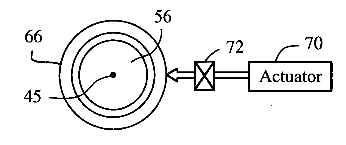
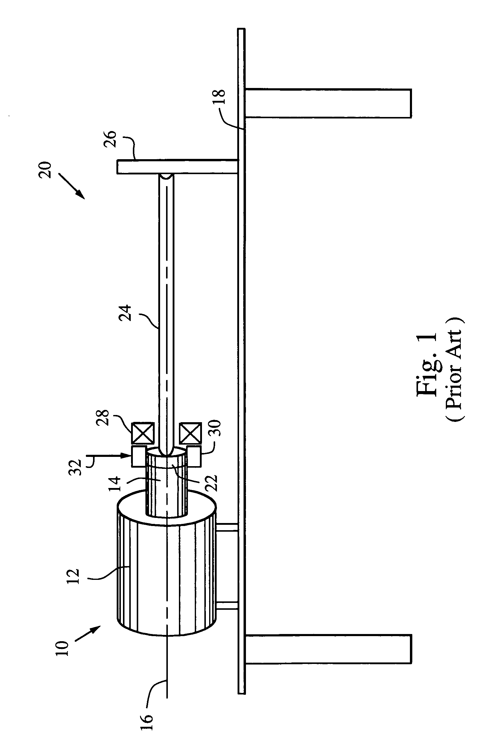
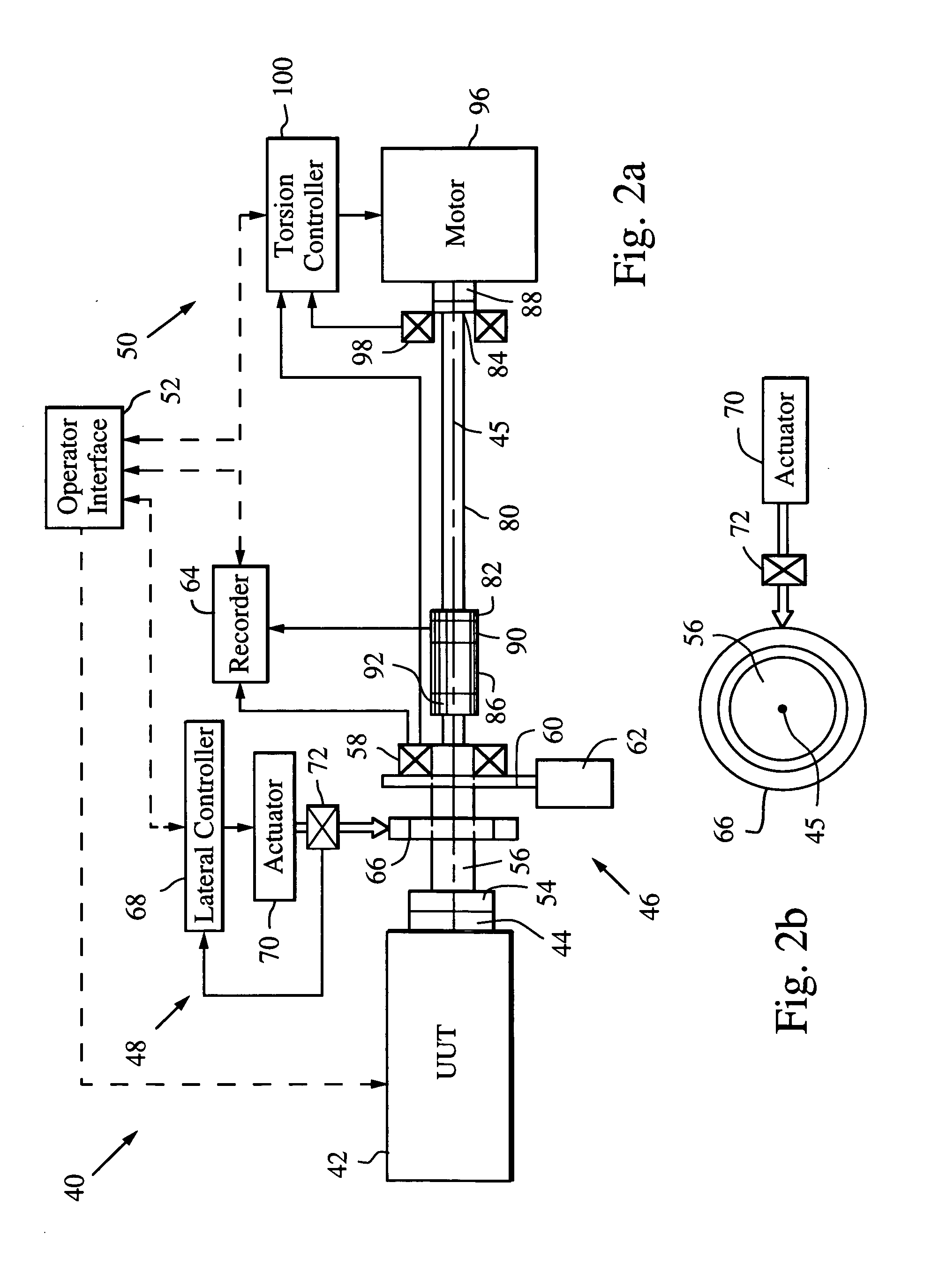
[0011] The application of a lateral load to the rotating shaft can produce forces that move the shaft in different directions. The induced motion can affect the accuracy of the encoder measurement and may damage the encoder or the torsion bar. The encoder. is suitably mounted on an isolation stage that constrains the encoder from rotating about the axis while allowing it to move in other directions in which the application of the lateral force induces motion. This preserves the accuracy of the encoder measurement and prevents the encoder from being damaged. The isolation stage includes a combination of linear and vertical slides and rotation bearings. A pair of flex couplings is suitably provided at either end of the torsion bar so that the lateral load is effectively transferred to the UUT without inducing a curvature in the torsion bar.
[0014] The DLF may be configured to apply no torsion load by leaving the opposite end of the torsion bar free to rotate or removing the torsion bar, to simultaneously apply a torsion load that is proportional to the amount of rotation by fixing the end of the torsion bar, or to simultaneously apply a dynamic torsion load. In the latter case, a motor applies torque to the free end of the torsion bar. Closed loop control is used to measure the applied torque and adjust the motor control. This approach allows the DLF to dynamically control both the torsion and lateral loads to more effectively reproduce desired acceptance tests such as torque-at-rate and real life conditions via nonlinear loads with a high response bandwidth.

Problems solved by technology

The induced motion can affect the accuracy of the encoder measurement and may damage the encoder or the torsion bar.

Method used


Image

  • Dynamic load fixture for rotary mechanical systems
  • Dynamic load fixture for rotary mechanical systems
  • Dynamic load fixture for rotary mechanical systems

Examples


Embodiment Construction

[0024] The present invention provides a dynamic load fixture (DLF) for applying a programmable time-varying lateral load to a rotary mechanical system and isolating the measurement of the angular displacement of its rotational output under load. Although the DLF may be configured to apply no torsion load by leaving the opposite end of the torsion bar free to rotate or removing the torsion bar, or to apply a torsion load that is proportional to the amount of rotation by fixing the end of the torsion bar, the DLF will be described in a configuration in which both dynamic lateral and torsion loads are applied. This configuration allows the DLF to more effectively reproduce desired acceptance tests and real life conditions.

[0025] As shown in FIGS. 2a and 2b, a dynamic load fixture (DLF) 40 is configured for testing a unit under test (UUT) 42 having a drive shaft 44 that rotates about an x-axis 45 (“roll”). The DLF comprises an encoder system 46 that measures the angular rotation of the...


PUM

PropertyMeasurementUnit
lateral forceaaaaaaaaaa
forceaaaaaaaaaa
degrees of freedomaaaaaaaaaa

Abstract

A dynamic load fixture (DLF) for testing a unit under test (UUT) includes a lateral load system that applies a time-varying lateral load profile to the UUT drive shaft and an encoder that measures its angular rotation. An isolation stage suitably constrains the encoder from rotating about the axis while allowing it to move in other directions in which the application of the lateral force induces motion. The lateral load system includes a load bearing around the drive shaft, an actuator that applies a lateral force to the load bearing, a force sensor for measuring the applied lateral force, and a lateral controller for adjusting a command signal to the actuator to implement a lateral load profile. The DLF may also include a torsion load system that applies a time-varying torsion load profile to the drive shaft.

Description

BACKGROUND OF THE INVENTION [0001] 1. Field of the Invention [0002] This invention relates to test fixtures for applying loads to a rotary mechanical system and more specifically to text fixtures for applying a dynamic lateral load and isolating the measurement of the angular displacement of the rotational output under load. [0003] 2. Description of the Related Art [0004] The use of rotary mechanical systems to power automobiles, drive robotics, actuate flight control systems on airplanes and missiles and many other mechanical systems is ubiquitous throughout our economy. The use of a motor to rotate a shaft to actuate these various systems is a cost effective and reliable way to convert electrical energy into a mechanical force. In many applications such as found in an automobile, the motor rotates the drive shaft at a high and relatively constant rate. Therefore, the shaft has a large range of motion but a relatively small frequency content. In other applications such as found in ...

Claims


Application Information

Patent Timeline
Patent Type & Authority Applications(United States)
IPC IPC(8): G01L3/10
CPCG01M13/027
Inventor DELAIR, CHARLES M.CLINE, R. BRIANOWAN, CHRISTOPHER P.BAIN, JASON M.STILSON, SHANE P.CROFT, DONALD E.
Owner RAYTHEON CO
Learn More