Braided stent and method for its manufacture

a stent and brad technology, applied in the field of brad stents and stentgrafts, can solve the problems of reducing radial strength, insufficient to adequately maintain an open passageway, and difficult intraluminal delivery and placement, and achieve the effect of increasing radial strength

Inactive Publication Date: 2006-04-06
BOSTON SCI SCIMED INC
View PDF11 Cites 54 Cited by
  • Summary
  • Abstract
  • Description
  • Claims
  • Application Information

AI Technical Summary

Benefits of technology

[0009] More specifically, and in a preferred embodiment, the stent of the present invention has a first plurality of braided filaments in one region, and an additional plurality of filaments added to the first plurality of filaments which are together braided to form a second region. The second plurality of filaments are present only in the second region. A preferred embodiment comprises a stent having a narrow region and a broader region with the broader region comprising more filaments than the narrow region such that increased radial strength is exhibited in the broader region. A more preferred stent of the present invention has a first plurality of filaments extending throughout the narrow region and the broader region, and a second plurality of filaments extending along only the broader region. The second plurality of filaments is preferably braided into the first plurality of filaments. In a still yet more preferred embodiment, the stent further comprises a transition region between the narrow region and the broader region. The transition region is comprised of the first plurality of filaments whose braiding increases in diameter from the narrow region to the broader region.

Problems solved by technology

Many of these braided stents have the problem, however, of either being too rigid such that intraluminal delivery and placement becomes difficult, or too flexible (at the cost of reducing radial strength) such that radial expansion forces exhibited at the site of treatment are insufficient to adequately maintain an open passageway through the site.
Moreover, by increasing the radial strength of a stent, one typically reduces flexibility, because the stent is more rigid.

Method used


Image

  • Braided stent and method for its manufacture
  • Braided stent and method for its manufacture
  • Braided stent and method for its manufacture

Examples


Embodiment Construction

[0021] The invention will next be illustrated with reference to the figures wherein similar numbers indicate the same elements in all figures. Such figures are intended to be illustrative rather than limiting and are included herewith to facilitate the explanation of the apparatus of the present invention.

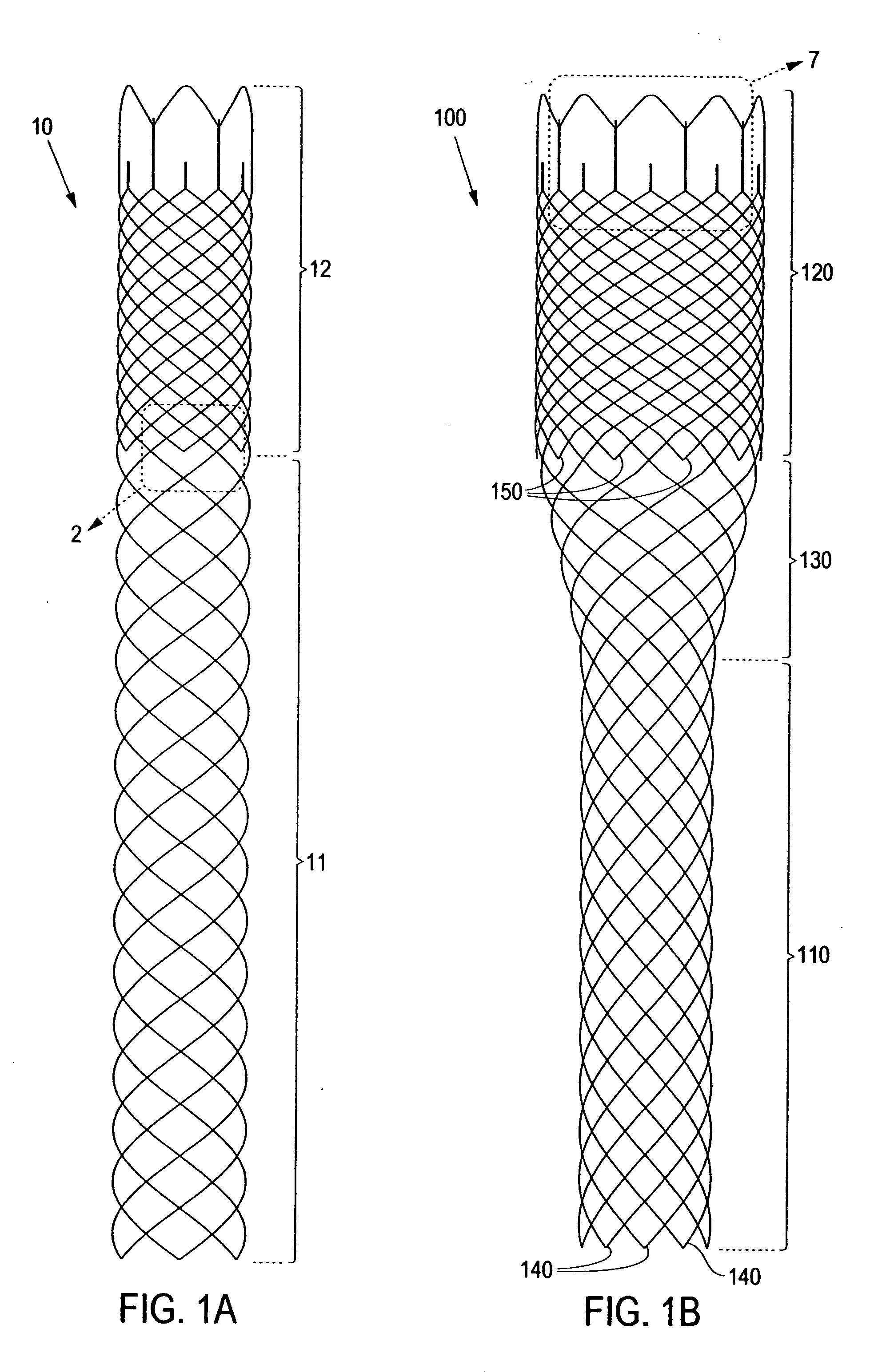
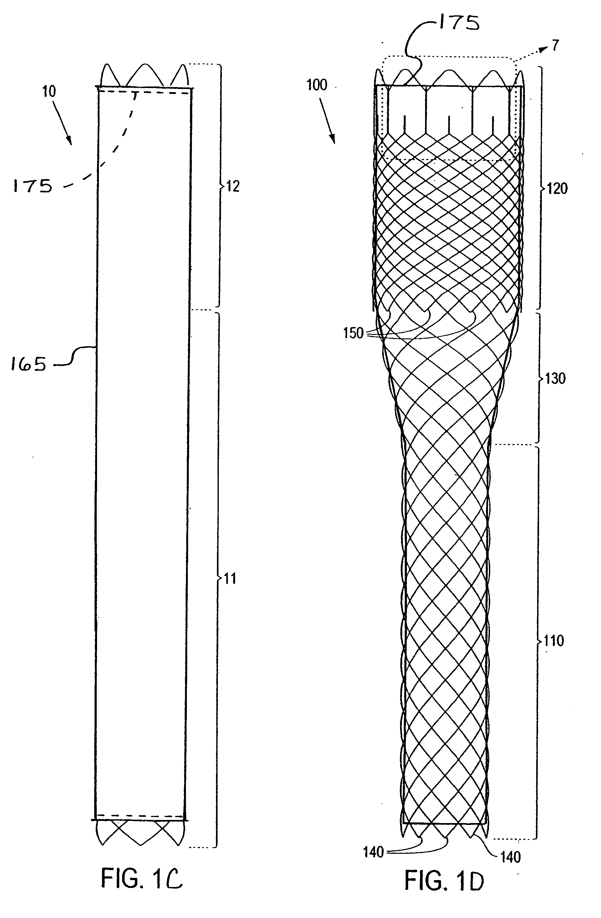
[0022] Referring to FIG. 1A, there is shown a braided stent 10 according to the present invention. For purposes of this invention, a braided stent is one formed by at least two sets of parallel continuous filaments, the two sets traversing the circumference of the stent in lengthwise but angularly intersecting directions. The two sets of filaments are interlaced or interwoven to form a tubular, supportive structure. The stent shown in FIG. 1A comprises a relatively flexible region 11 and a relatively rigid region 12 (having greater radial strength than flexible region 11). Rigid region 12 comprises more filaments than flexible region 11 and therefore exhibits greater radial streng...


PUM


Abstract

A stent and method for making the stent are provided. The stent comprises regions of differing numbers of braided filaments to provide a stent with different dimensions and / or properties in different regions along the stent length. A preferred stent comprises a first and second plurality of braided filaments each braided together. The second plurality of braided filaments is braided into the first plurality of braided filaments to form a region of different properties than the first. A preferred embodiment is a stent having a narrower diameter along a more flexible region and a broader diameter along a more rigid region. Also included is a method of constructing a braided stent in accordance with the above. The method comprises the steps of braiding a first plurality of filaments to form the flexible portion, combining a second plurality of filaments to the first plurality of filaments, and then braiding the second plurality of filaments with the first plurality of filaments to form the more rigid region from the combination of the first and second plurality of filaments, wherein the second plurality of filaments are braided only in the rigid region.

Description

CROSS-REFERENCE [0001] This application is a divisional application of application Ser. No. 10 / 295,454, filed Nov. 15, 2002 which is incorporated herein by reference in its entirety and for all purposes.TECHNICAL FIELD [0002] This invention relates generally to stents and stent-grafts, and more specifically, to braided stents and stent-grafts having segments of different strength and rigidity along the length, and / or different diameters of varying or constant strength and rigidity along the length. BACKGROUND OF THE INVENTION [0003] A stent is an elongated device used to support a luminal wall. A stent, along with a graft cover or liner, together provide an unobstructed conduit for fluid flow in the area of a stenosis. Such a stent-graft would typically have a tubular graft layer covering, or lining, the inside or outside of the stent (or both), thus providing a fluid conduit to bypass a stenosis or otherwise diseased body passageway. [0004] Various types of stent architectures are ...

Claims


Application Information

Patent Timeline
Patent Type & Authority Applications(United States)
IPC IPC(8): D04C1/00A61F2/88A61F2/00A61F2/90
CPCA61F2/90A61F2250/0018A61F2250/0039D10B2509/06D04C3/48A61F2230/0054A61F2230/0067D04C1/06D10B2403/0333
Inventor MCCULLAGH, ORLAQUINN, WILLIAM R.
Owner BOSTON SCI SCIMED INC
Why Eureka
Try Eureka