
Cathodic protection system for underground storage tank

a protection system and underground storage technology, applied in the field of cathodic protection system and method, can solve the problems of system adverse effects, corrosion on the outer surface of both buried and above-ground pipelines, and common metal surfaces,

Inactive Publication Date: 2006-04-06
HOUST
View PDF11 Cites 21 Cited by
  • Summary
  • Abstract
  • Description
  • Claims
  • Application Information

AI Technical Summary

Benefits of technology

[0013] If the output is above a defined value, the as yet to be installed automatic control DC power supply has sufficient voltage capacity to deliver the...

Problems solved by technology

Metallic surfaces, such as are common in the field of pipelines and related structures, such as buried tanks and distribution systems, are adversely affected by numerous corrosive electrolytic fluids that contact these surfaces.
For example, in the natural gas and petroleum industries, corrosion occurs extensively on the outer surface of both buried and above-ground pipelines.
Despite the use of such coating compositions and materials, external corrosion of underground tanks is still a concern when there is a breach of the coating or when such coatings have been poorly applied or not applied at all.
Even when cathodic protection is used, corrosion and defects usually still occur.
Coating defects generally take the form of either exposed bare steel or a disbandment where the coating remains intact but a gap is formed between it and the bare steel.
The above described cathodic protection methods are often complex and cumbersome to install, typically requiring specialized equipment and personnel to be present during the installation of a tank and for detailed filed surveys or soil testing to be performed, thereby adding to the cost of such a system.

Method used


Image

  • Cathodic protection system for underground storage tank
  • Cathodic protection system for underground storage tank
  • Cathodic protection system for underground storage tank

Examples


Embodiment Construction

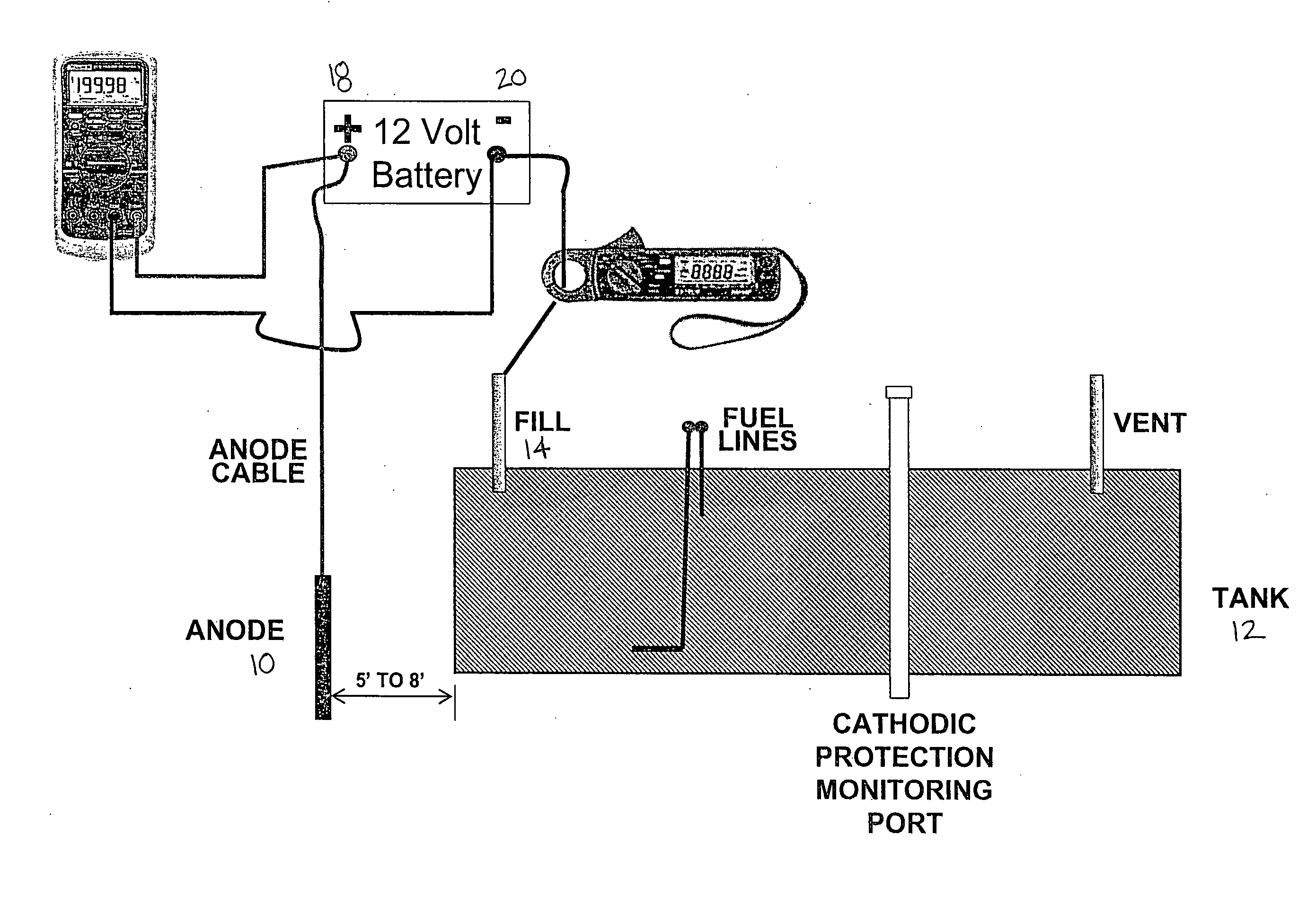
[0017] The present exemplary embodiments relate to a system and method for providing impressed current cathodic protection to an underground storage tank or pipe. By way of example, the exemplary embodiments will be described with reference to an underground heating oil storage tank for home or residential use, which applicants envision as the primary market for the present invention. However, the invention is in no way limited to such tanks but in fact can be extended to any underground storage tank or pipe for holding or transporting a material. For convenience, applicants may make reference herein when describing the present embodiments to a HOUST system, which is an acronym for Home Oil Underground Storage Tank. The present described embodiments can be employed in conjunction with both new and existing HOUST systems. In addition, although the described embodiments make reference to underground tanks, above ground metallic structures in need of cathodic protection are also amenab...


PUM


Abstract

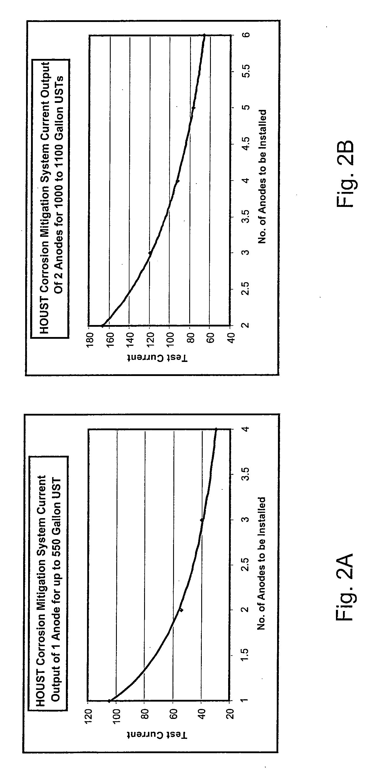
There is provided a method for implementing a cathodic protection system for an underground storage tank. A DC voltage source provides a test current between the installed anode and storage tank resulting in the flow of electrical current. If the output is above a defined value, an automatic control DC power supply has sufficient voltage capacity to deliver the required current. If the anode test currents fall below the required minimum current, additional anode(s) are installed as set forth in a pre-engineered table. The method allows for the installation of a cathodic protection system by technicians and other non-experts.

Description

BACKGROUND [0001] The present exemplary embodiments relate to a cathodic protection system and method. It finds particular application in conjunction with underground storage tanks, and will be described with particular reference thereto. However, it is to be appreciated that the present exemplary embodiment is also amenable to other like applications. [0002] Metallic surfaces, such as are common in the field of pipelines and related structures, such as buried tanks and distribution systems, are adversely affected by numerous corrosive electrolytic fluids that contact these surfaces. For example, in the natural gas and petroleum industries, corrosion occurs extensively on the outer surface of both buried and above-ground pipelines. [0003] In order to reduce, or preferably eliminate, this undesirable metallic surface corrosion, anti-corrosion protective coatings have been extensively used in the underground storage tank industry. These ubiquitous anti-corrosion protective coatings fr...

Claims


Application Information

Patent Timeline
IPC IPC(8): C23F13/00
CPCC23F13/02C23F13/04
Inventor BUSHMAN, JAMES B.BURKE, N. DENNISCARLSON, WILLIAM P.
Owner HOUST
Learn More