System and method for power conversion

a power converter and power technology, applied in the field of power converter systems, can solve the problems of additional equipment, reducing the overall efficiency of the system, and high cost of typical two-stage power converters for low-power applications

Inactive Publication Date: 2006-04-06
GENERAL ELECTRIC CO
View PDF10 Cites 33 Cited by
  • Summary
  • Abstract
  • Description
  • Claims
  • Application Information

AI Technical Summary

Benefits of technology

[0005] Briefly, in accordance with one aspect of the technique, a power converter system is provided for supplying power to an electrical load. The power converter system includes a power converter circuit adapted to perform an AC-DC power conversion and comprising a plurality of semiconductor switches having reverse voltage withstand capability. The power converter system also includes a power factor control loop for regulating power factor, a DC voltage control loop for regulating the output DC voltage and a controller coupled to the power converter circuit for regulating switching of the plurality of semiconductor switches based on a feedback signal received from at least one of the power factor control loop and the DC voltage control loop.

Problems solved by technology

However, typical two stage power converters are costly for low power applications.
In addition, compliance to standards, such as IEEE 519, requires additional equipment that is expensive, bulky and generally reduces the overall efficiency of the system.
Hence, present methods have limitations for achieving high level of power factor and low harmonic performance for AC-DC step down function and tend to be expensive and less efficient.

Method used


Image

  • System and method for power conversion
  • System and method for power conversion
  • System and method for power conversion

Examples


Embodiment Construction

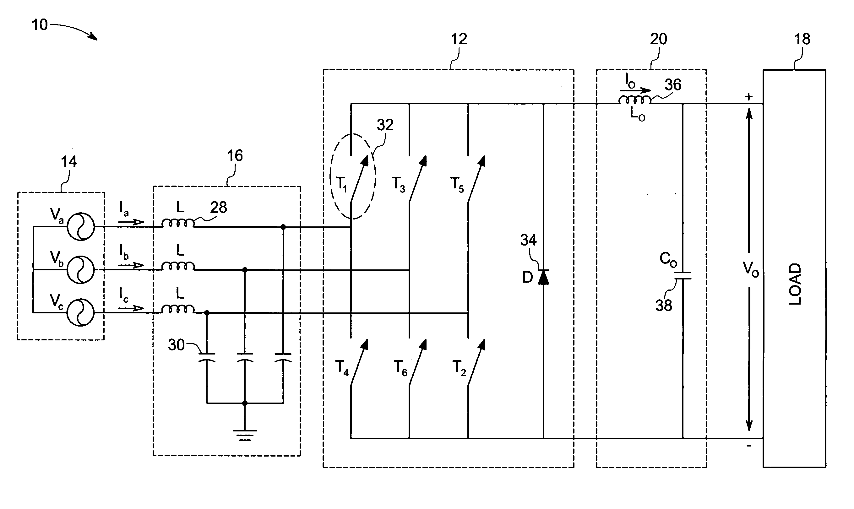
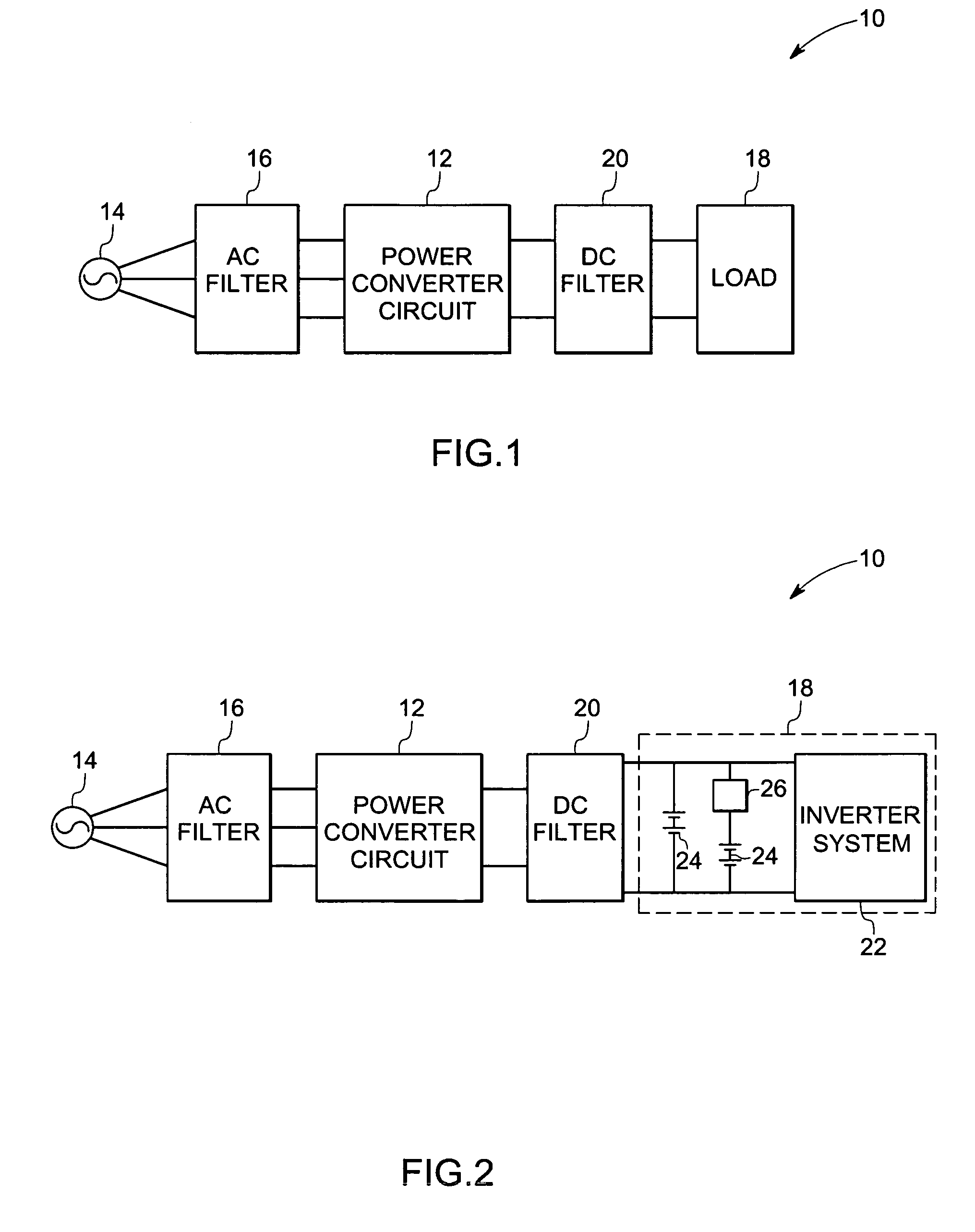
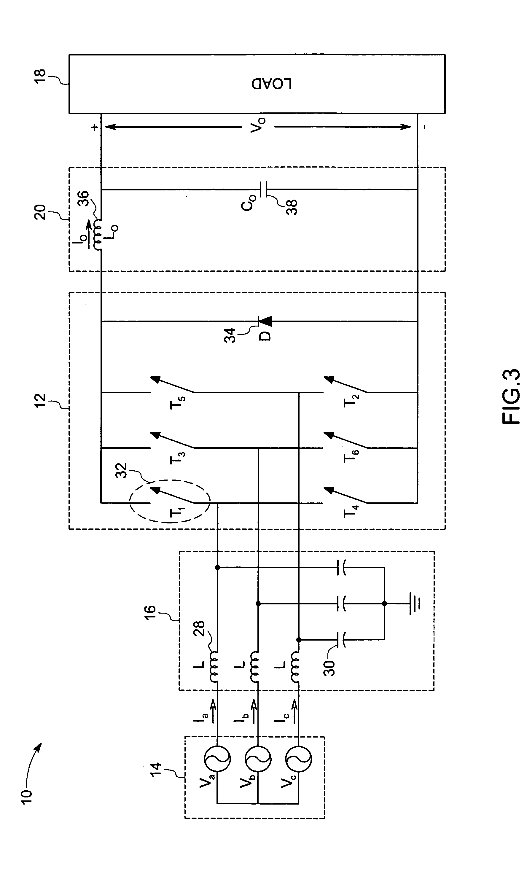
[0016]FIG. 1 is a block diagram of a power converter system 10 implemented according to one aspect of the invention. The power converter system 10 includes a power converter circuit 12 for converting an input AC power to a DC power. The AC power from an AC source 14 is fed into the power converter circuit 12 via an AC filter 16. In the illustrated embodiment, the AC source 14 is a three-phase power from the power grid. Alternatively, the AC source 14 may be a single-phase power supply, multi-phase power supply or others. The AC filter 16 minimizes the harmonics generated by the power converter circuit 12 from entering into the AC source 14. The DC power from the power converter circuit 12 is fed to an electrical load 18 through a DC filter 20.

[0017] The power converter system 10 is configured to supply DC power to an electrical load 18, such as resistive loads, dc motors or any other DC loads. Alternatively, the power converter system 10 may be coupled to various other DC fed syste...


PUM


Abstract

A power converter system is provided for supplying power to an electrical load. The power converter system includes a power converter circuit adapted to perform an AC to DC power conversion and an active clamp circuit coupled to the power converter circuit for regulating DC bus voltage overshoots. The power converter circuit is configured from a plurality of semiconductor switches having reverse voltage withstand capability.

Description

BACKGROUND [0001] The invention relates generally to a power converter system and more specifically to an AC to DC step down power converter system. [0002] Power converters are used in a wide variety of applications. Equipment such as UPS's, battery chargers, AC-DC power supplies and others use an AC-DC power converter to convert incoming AC, typically from a power grid, to DC power output. Typically, techniques such as PWM (pulse width modulation) boost conversion have been successfully deployed to produce AC-DC power converters with high power factor and sinusoidal input currents. However the DC voltage in such cases is higher than the peak value of the AC supply (boost function). In a wide variety of applications, such as those mentioned above, the DC voltage required is usually lower than the peak value of the AC supply (step down function). [0003] Current techniques and devices employed for achieving a AC-DC step down function, such as thyristor controlled rectifiers, input ste...

Claims


Application Information

Patent Timeline
Patent Type & Authority Applications(United States)
IPC IPC(8): H02H7/125
CPCH02M7/219H02M1/4233Y02B70/10
Inventor GHOSH, RAJESHPHANSALKAR, BANSIDHAR JAGANNATHCOLOMBI, SILVIO
Owner GENERAL ELECTRIC CO
Why Eureka
Try Eureka