
Converter and control method thereof

a technology of converters and control methods, applied in the field of converters, can solve the problems of limiting the development of flyback converters with smaller sizes and a higher frequency

Active Publication Date: 2018-03-01
DELTA ELECTRONICS INC
View PDF3 Cites 28 Cited by
  • Summary
  • Abstract
  • Description
  • Claims
  • Application Information

AI Technical Summary

Benefits of technology

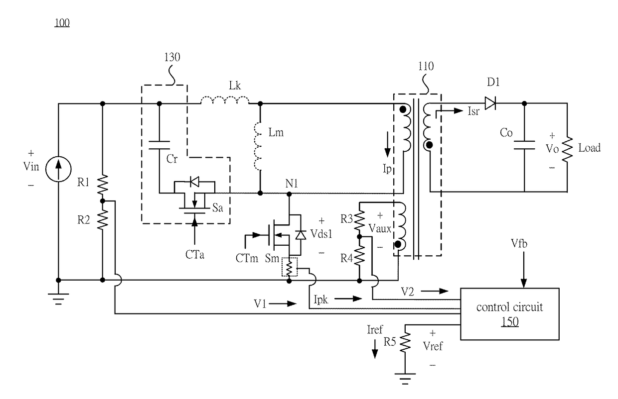
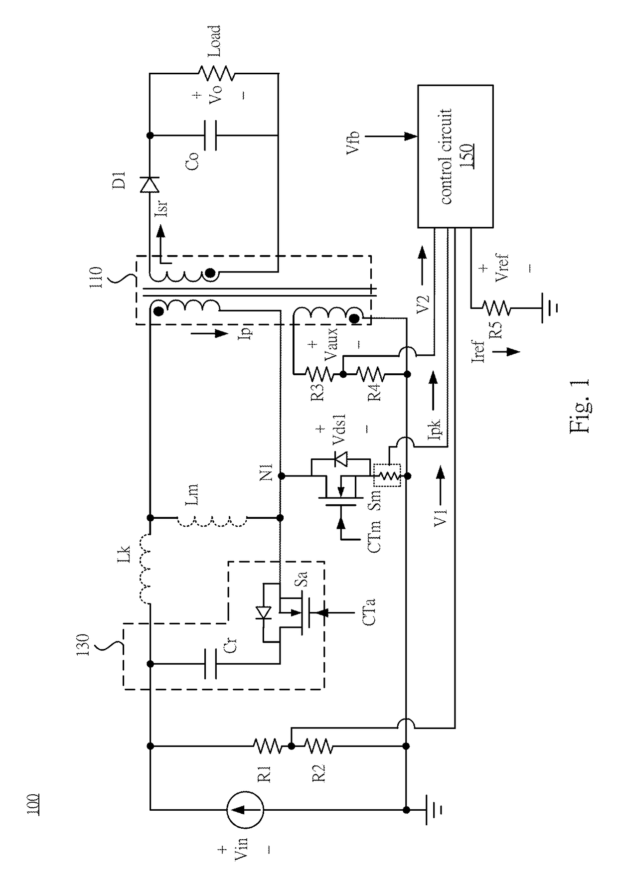
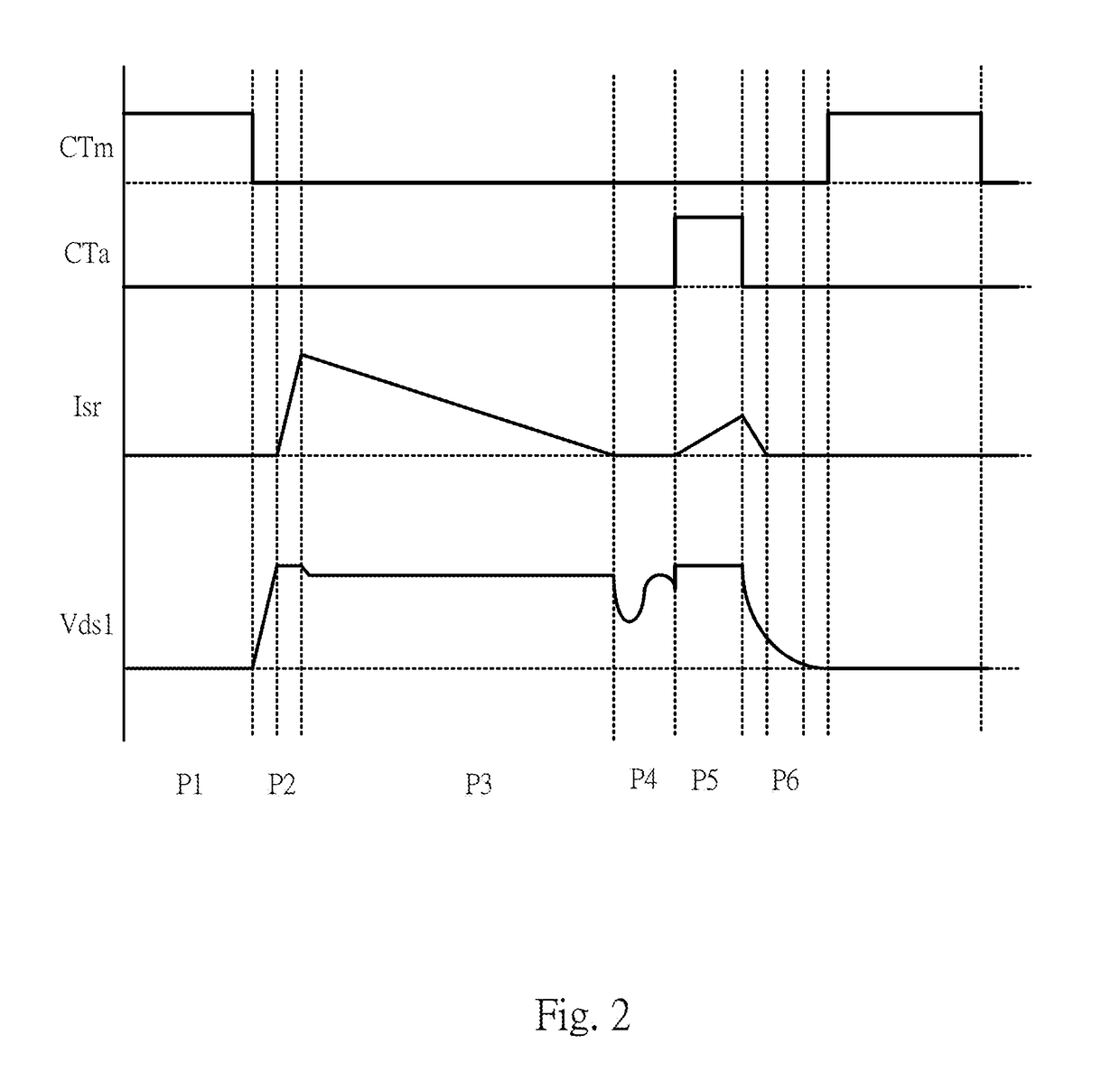
The present invention is a converter that includes a transformer, a main switch, an active clamp circuit and a control circuit. The active clamp circuit is coupled in parallel to the two terminals of the primary winding or the two terminals of the main switch and is configured to clamp the voltage across the main switch when the main switch is off. The control circuit is configured to output an auxiliary switch control signal to control the auxiliary switch to be turned on when the voltage across the main switch is at one of the 1st to Nth peaks of the resonant voltage, in which N is an integer. This invention has improved the efficiency and stability of converters, especially in high-speed applications.

Problems solved by technology

However, the leakage loss of the transformer and the turn-on loss of the main switch limit the development of the Flyback converter with smaller sizes and a higher frequency.

Method used


Image

  • Converter and control method thereof
  • Converter and control method thereof
  • Converter and control method thereof

Examples


Embodiment Construction

[0016]Reference will now be made in detail to embodiments of the present disclosure, examples of which are described herein and illustrated in the accompanying drawings. While the disclosure will be described in conjunction with embodiments, it will be understood that they are not intended to limit the disclosure to these embodiments. On the contrary, the disclosure is intended to cover alternatives, modifications and equivalents, which may be included within the spirit and scope of the disclosure as defined by the appended claims. It is noted that, in accordance with the standard practice in the industry, the drawings are only used for understanding and are not drawn to scale. Hence, the drawings are not meant to limit the actual embodiments of the present disclosure. In fact, the dimensions of the various features may be arbitrarily increased or reduced for clarity of discussion. Wherever possible, the same reference numbers are used in the drawings and the description to refer to...


PUM


Abstract

A converter includes a transformer, a main switch, an active clamp circuit, and a control circuit. The transformer includes a primary winding and a secondary winding, and is configured to receive an input voltage and output an output voltage to a load. The main switch is coupled between the primary winding and a primary ground terminal. The active clamp circuit includes an auxiliary switch and a clamp capacitor. The auxiliary switch is coupled to the clamp capacitor in series, and the active clamp circuit is coupled in parallel to the two terminals of the primary winding or the main switch, and is configured to clamp the voltage across the main switch when it is OFF. The control circuit outputs an auxiliary switch control signal to turn on the auxiliary switch when the voltage across the main switch is at its first peak of the resonant voltage.

Description

RELATED APPLICATIONS[0001]This application claims priority to China Application Serial Number 201610790921.1, filed Aug. 31, 2016, which is herein incorporated by reference.BACKGROUNDTechnical Field[0002]The present disclosure relates to a converter, and in particular, to a Flyback converter.Description of Related Art[0003]Flyback converters are widely applied in low power applications, especially in power devices lower than 100 W, due to characteristics of a simple circuit structure, electrical isolation between the input and output stage, and low cost.[0004]With the widespread use of switching power supplies in portable devices such as notebooks, tablets, and smartphones in recent years, there is a trend to develop switching power supplies with smaller sizes, higher efficiency and higher frequency.[0005]However, the leakage loss of the transformer and the turn-on loss of the main switch limit the development of the Flyback converter with smaller sizes and a higher frequency.SUMMAR...

Claims


Application Information

Patent Timeline
IPC IPC(8): H02M3/335
CPCH02M3/33569H02M3/33523H02M3/33592H02M1/0009H02M3/01H02M3/33507Y02B70/10H02M1/342
Inventor SONG, HAI-BINXU, DAO-FEIZHOU, JIANYANG, LE-YANGFU, QIZHANG, JIN-FA
Owner DELTA ELECTRONICS INC
Learn More