Adaptive active clamp of flyback power converter with high efficiency for heavy load and light load

a technology of heavy load and light load, applied in the control circuit of the flyback power converter with the active clamp, can solve the problems of high power loss at the light load, and the traditional active clamp circuit can only achieve high efficiency for the heavy load, and achieve the effect of high efficiency

Active Publication Date: 2014-08-21
SEMICON COMPONENTS IND LLC
View PDF12 Cites 29 Cited by
  • Summary
  • Abstract
  • Description
  • Claims
  • Application Information

AI Technical Summary

Benefits of technology

[0005]It is an objective of the present invention to provide a control circuit for the flyback power converter. It can make the flyback power converter achieve high efficiency in the heavy load and the light load.

Problems solved by technology

Nevertheless, the traditional active-clamp circuit can only achieve high efficiency for the heavy load.
The drawback of the traditional active-clamp circuit is the higher power loss at the light load because of the high circulated current.

Method used


Image

  • Adaptive active clamp of flyback power converter with high efficiency for heavy load and light load
  • Adaptive active clamp of flyback power converter with high efficiency for heavy load and light load
  • Adaptive active clamp of flyback power converter with high efficiency for heavy load and light load

Examples


Embodiment Construction

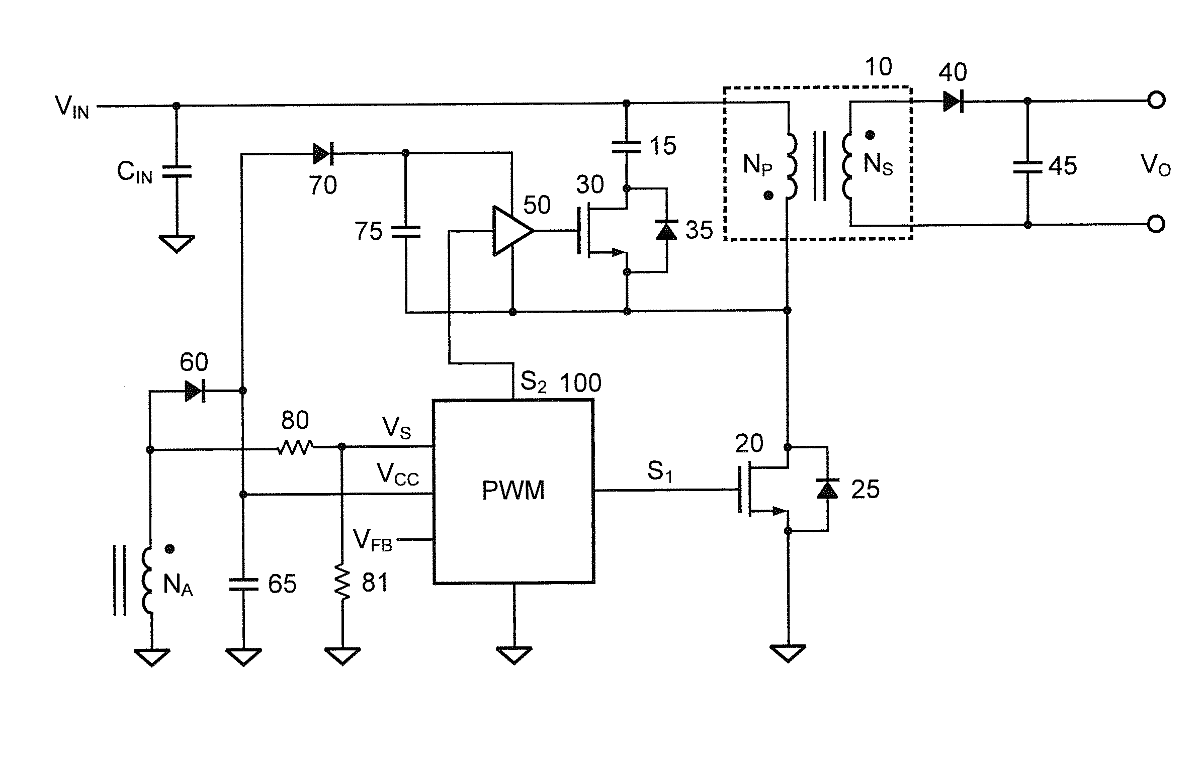
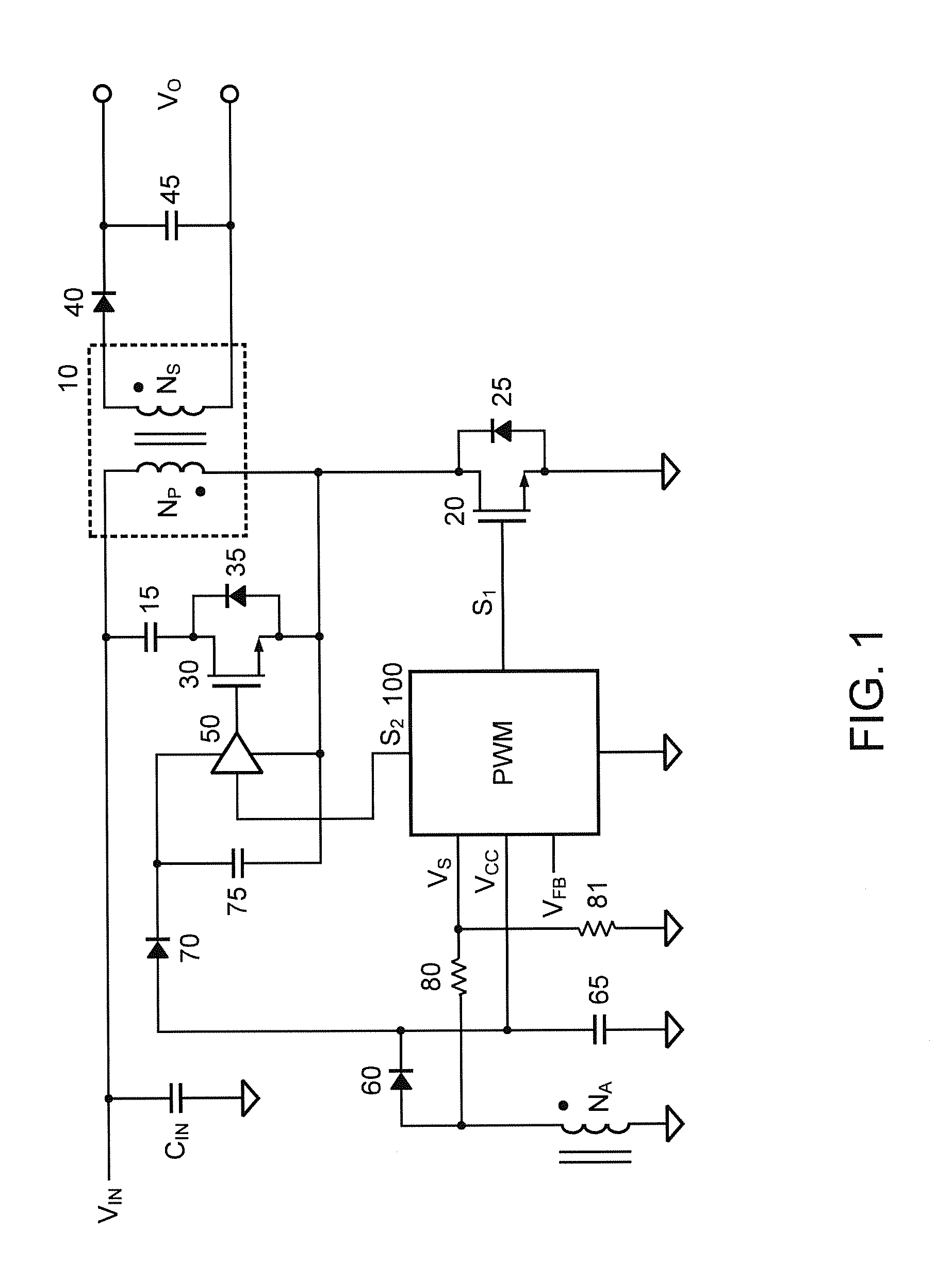
[0025]FIG. 1 is a circuit diagram of an embodiment of the power converter in accordance with the present invention. It is a flyback power converter with active clamp. The power converter includes a transformer 10 having a primary winding NP and a secondary winding NS. A first terminal of the primary winding NP is coupled to one terminal of an input capacitor CIN and receives an input voltage VIN. The other terminal of the input capacitor CIN is coupled to a ground. The control circuit includes transistors 20, 30, a capacitor 15, a high-side drive circuit 50, and a controller (PWM) 100.

[0026]The transistor 20 is coupled between a second terminal of the primary winding NP and the ground. The transistor 20 is a low-side transistor to switch the primary winding NP of the transformer 10 for regulating an output VO of the power converter. A parasitic diode 25 is a body diode that is coupled to the transistor 20 in parallel. The output VO is generated through a rectifier 40 and an output c...


PUM


Abstract

A control circuit of a flyback power converter according to the present invention comprises a low-side transistor, an active-damper, a high-side drive circuit, and a controller. The low-side transistor is coupled to switch a transformer. The active-damper is coupled in parallel with the transformer. The high-side drive circuit is coupled to drive the active-clamper. The controller generates a switching signal and an active-clamp signal. The switching signal is coupled to drive the low-side transistor. The switching signal is generated in accordance with a feedback signal for regulating an output of the flyback power converter. The active-clamp signal is coupled to control the high-side drive circuit and the active-damper. The active-clamp signal is generated in response to a demagnetizing time of the transformer. The pulse number of the active-clamp signal is less than the pulse number of the switching signal in a light load condition.

Description

BACKGROUND OF THE INVENTION[0001]1. Field of the Invention[0002]The present invention relates to power converter, and more particularly, relates to the control circuit of the flyback power converter with active clamp.[0003]2. Description of the Related Art[0004]Flyback power converters have been widely used to provide power supplies for electronic products, such as home appliances, computers, battery charger etc. An active-clamp circuit has developed for the flyback power converter, that increases the efficiency of the flyback power converter. Nevertheless, the traditional active-clamp circuit can only achieve high efficiency for the heavy load. The drawback of the traditional active-clamp circuit is the higher power loss at the light load because of the high circulated current. The objective of this invention is to improve the efficiency of the flyback power converter by recycling the leakage inductance's energy of the transformer in the light load, and achieving the soft switching...

Claims


Application Information

Patent Timeline
Patent Type & Authority Applications(United States)
IPC IPC(8): H02M3/335H02M1/00
CPCH02M3/33507H02M3/33576H02M1/0032Y02B70/10
Inventor YANG, TA-YUNGHSIEH, CHIH-HSIENWEI, KAI-FANGCHEN, JUNG-SHENG
Owner SEMICON COMPONENTS IND LLC
Why Eureka
Try Eureka