
Radio base device reference signal, allocation method, and reference signal allocation program

a radio base device and reference signal technology, applied in the direction of electrical equipment, radio transmission, connection management, etc., can solve the problems of deteriorating communication quality, affecting the quality of communication, and conventional css does not adequately address the problem of interference with users in another cell, so as to improve the quality of call and improve the interference between users

Active Publication Date: 2006-04-06
KYOCERA CORP
View PDF28 Cites 11 Cited by
  • Summary
  • Abstract
  • Description
  • Claims
  • Application Information

AI Technical Summary

Benefits of technology

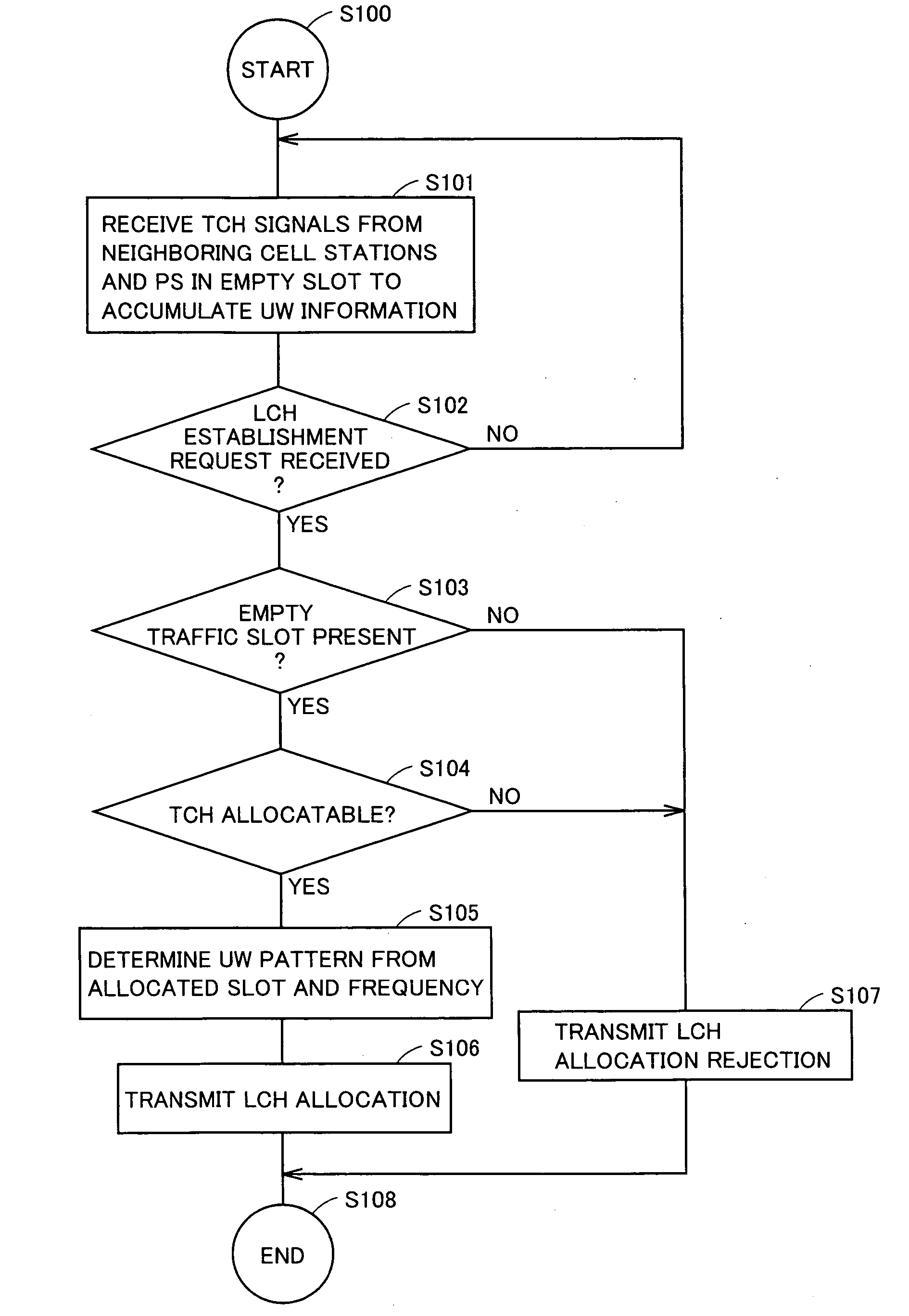
The present invention provides a method and apparatus for allocating reference signals in a mobile communication system. The technical effect of the invention is to prevent deterioration in call quality and interference between users caused by mutual interference between PSs in adjacent cells. This is achieved by searching for a reference signal already used in a neighboring cell station and storing it for later use in a connection request from a terminal device. The reference signal allocation method includes steps of receiving a communication signal between a neighboring cell station and a terminal device, analyzing the reference signal in use, and allocating a different reference signal to the terminal device based on the cell station number assigned to each cell station.

Problems solved by technology

The above-described correlation synchronization, however, is based on the premise that the CS receives a signal from a single PS, and it is not adapted to a case in which the CS receives signals of the same frequency from two PSs in an overlapped manner.
If synchronous positions of the reception signals from the PSs of the plurality of users coincide with one another, reference signal sections of the reception signals overlap with one another and the users cannot be identified or separated from one another, resulting in interference among the users.
Since the synchronous position of the signal received from the desired PS cannot be specified, interference also occurs between users in different cells, resulting in deterioration in communication quality.
There still remains a problem, however, that the conventional CSs do not sufficiently address the problem of interference with users in another cell.

Method used


Image

  • Radio base device reference signal, allocation method, and reference signal allocation program
  • Radio base device reference signal, allocation method, and reference signal allocation program
  • Radio base device reference signal, allocation method, and reference signal allocation program

Examples


first embodiment

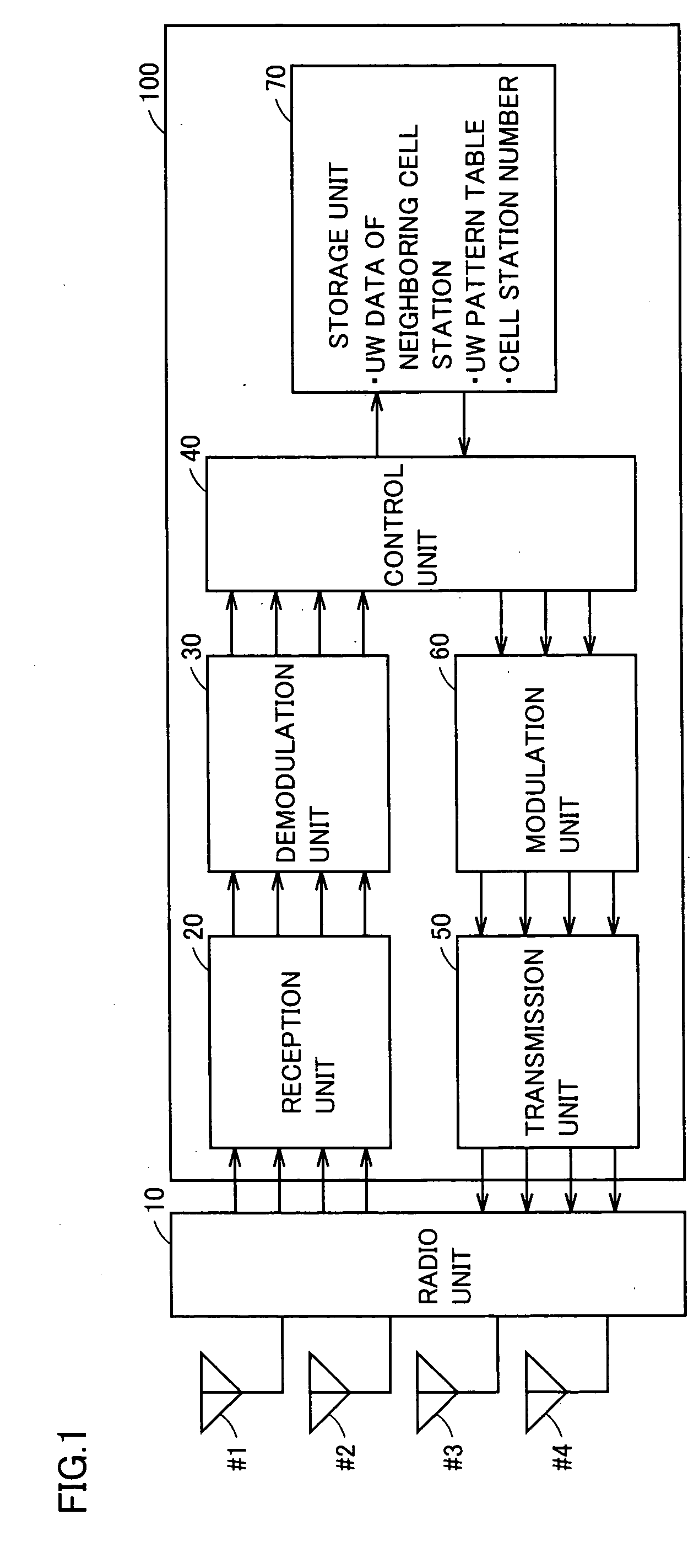
[0057]FIG. 1 is a schematic block diagram showing a configuration of a radio cell station according to a first embodiment of the present invention.

[0058] Referring to FIG. 1, the radio cell station apparatus includes a radio unit 10, a plurality of antennas (four antennas of antennas #1 to #4, for example), a reception unit 20, a demodulation unit 30, a control unit 40, a demodulation unit 30, a transmission unit 50, a modulation unit 60, and a storage unit 70.

[0059] Antennas #1 to #4 are connected to radio unit 10.

[0060] In reception, signals received by antennas #1 to #4 are provided to reception unit 20 through radio unit 10. The reception signals provided to reception unit 20 are subjected to various types of analog signal processing such as amplification and frequency conversion, and converted to digital signals by an A / D converter (not shown). In addition, reception unit 20 separates and extracts a signal of each user under the control of control unit 40. The separated and ...

second embodiment

[0107]FIG. 7 schematically shows a form in which a plurality of PSs are connected for each of CSs.

[0108] A method of allocating a unique word by a radio cell station apparatus of a second embodiment is conceptually described in connection with FIG. 7.

[0109] Referring to FIG. 7, like FIG. 4, the boundary in which radio waves from each of cell stations CS1 to CS5 are receivable is indicated by each of concentric circles 101 to 105 having the CS at the center. In FIG. 7, because of a high density of cell stations, concentric circles 101 to 105 overlap each other.

[0110] It is noted that, in circles 101 to 105 each, a plurality of user PSs are located and connected at a predetermined frequency of the CS in respective time slots.

[0111] Here, the radio cell station apparatus of the second embodiment differs from the radio cell station apparatus of the first embodiment in that respective CSs of the second embodiment have cell station numbers (BS) different from each other.

[0112] For ex...


PUM


Abstract

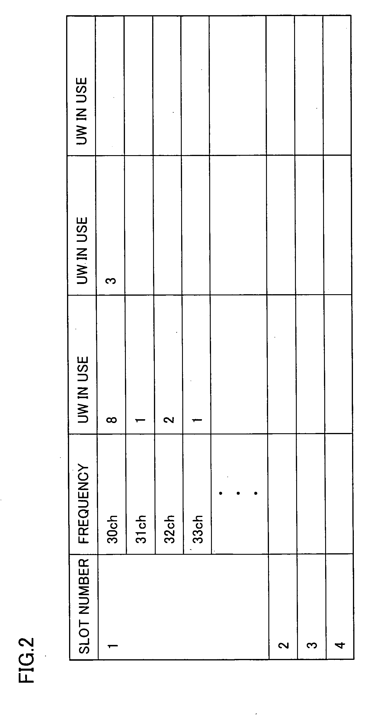
A CS searches in advance for information about unique words used by neighboring CSs to hold the information in a storage unit. When an LCH establishment request is made by a PS in the cell of the CS, it is confirmed whether or not there is an empty traffic slot. Further, with reference to the unique word information of the neighboring CSs of the same frequency and the same slot as the empty slot to be allocated, an unused unique word pattern is allocated.

Description

TECHNICAL FIELD [0001] The present invention relates to a radio cell station apparatus, a reference signal allocation method and a reference signal allocation program in a mobile communication system, and more particularly to a radio cell station apparatus, a reference signal allocation method and a reference signal allocation program for allocating a reference signal to a terminal device that makes a connection request. BACKGROUND ART [0002] Recently, in a rapidly-developing mobile communication system, for an improvement of efficiency in use of radio wave frequencies, various multiple access systems have been proposed that allow a plurality of users to share a radio transmission path and conduct communications simultaneously, and are now partially in practical use. [0003] For example, PHS (Personal Handyphone System) generally employs, as a method of splitting a transmission channel, TDMA (Time Division Multiple Access) that divides a radio channel with respect to time. [0004] The...

Claims


Application Information

Patent Timeline
Patent Type & Authority Applications(United States)
IPC IPC(8): H04B7/212H04J99/00H04W24/00H04W72/04H04W88/08
CPCH04W24/00H04W88/08H04W76/02H04W72/0466H04W76/10
Inventor ITO, TADAYOSHI
Owner KYOCERA CORP
Learn More