Stereo reproduction apparatus

a reproduction apparatus and stereo technology, applied in the direction of electrical apparatus, broadcast receiving circuits, two-channel systems, etc., can solve the problems of low receiving electric field strength, distortion of signal components, deterioration in separation and sound quality, etc., to suppress the deterioration of separation and sound quality

Active Publication Date: 2018-03-06
PANASONIC INTELLECTUAL PROPERTY CORP OF AMERICA
View PDF4 Cites 0 Cited by
  • Summary
  • Abstract
  • Description
  • Claims
  • Application Information

AI Technical Summary

Benefits of technology

[0004]One non-limiting and exemplary embodiment provides a stereo reproduction apparatus that suppresses deterioration in separation and sound quality even under a situation with a low receiving electric-field strength.
[0006]The present disclosure makes it possible to suppress deterioration in separation and sound quality even under a situation with a low receiving electric-field strength.

Problems solved by technology

While the non-linear processing is highly effective in eliminating noise, it imparts distortions to signal components contained in a stereo sum signal and in a stereo difference signal and undesirably invites deterioration in separation and sound quality.
In particular, the distortions of the signal components increase under a situation with a low receiving electric-field strength.
Therefore, Japanese Unexamined Patent Application Publication No. 2014-146942 undesirably invites deterioration in separation and sound quality under a situation with a low receiving electric-field strength.

Method used


Image

  • Stereo reproduction apparatus
  • Stereo reproduction apparatus
  • Stereo reproduction apparatus

Examples


embodiment 1

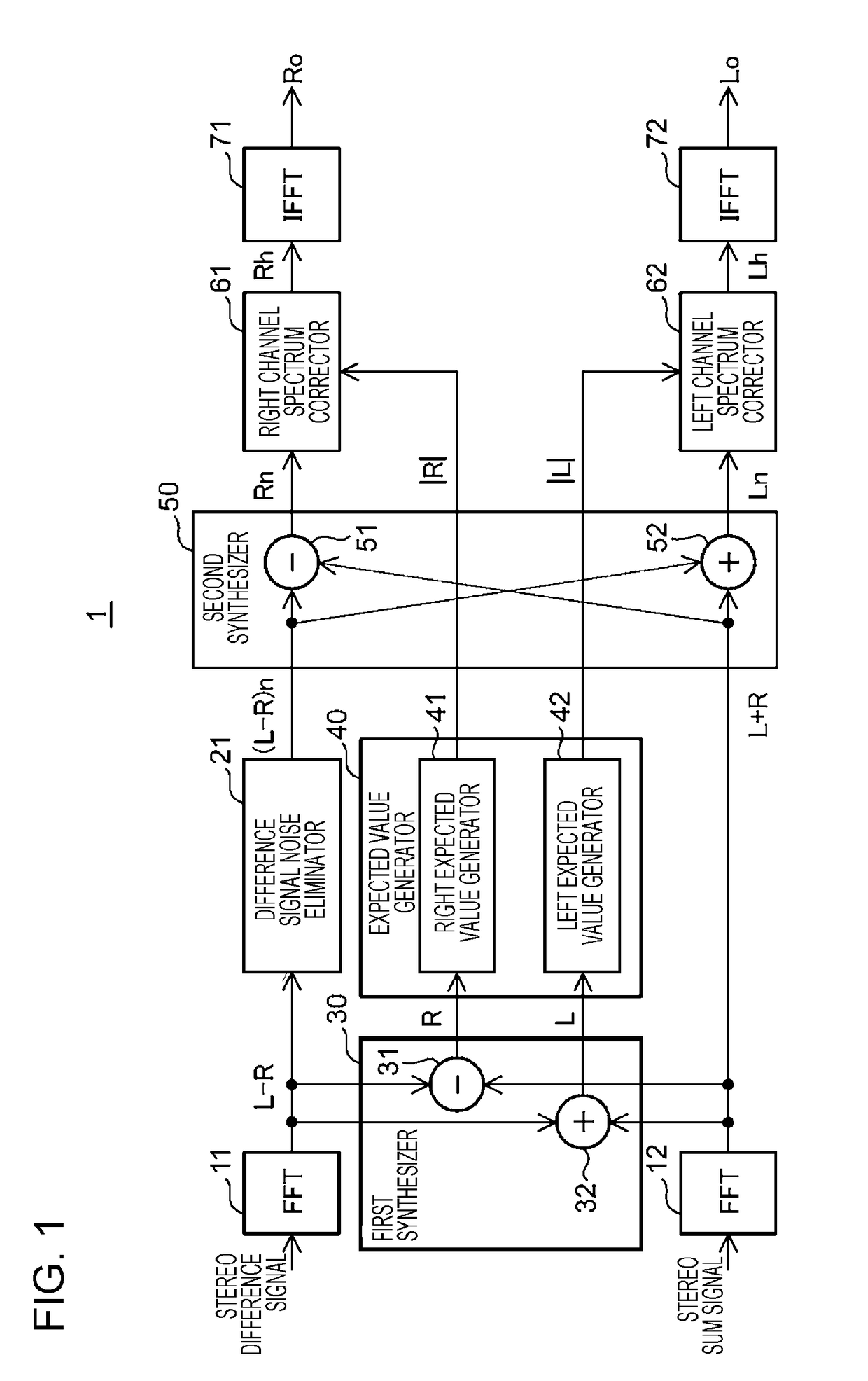
[0100]FIG. 1 is a block diagram showing an example of a configuration of a stereo reproduction apparatus 1 according to Embodiment 1 of the present disclosure. The stereo reproduction apparatus 1 is an apparatus for reproducing a digital FM stereo signal. The stereo reproduction apparatus 1 includes converters 11 and 12, a difference signal noise eliminator 21, a first synthesizer 30, an expected value generator 40, a second synthesizer 50, a right channel spectrum corrector 61, a left channel spectrum corrector 62, and reverse converters 71 and 72. The FM stereo signal is constituted by an FM composite signal containing a stereo sum signal and a stereo difference signal. The stereo sum signal and the stereo difference signal are extracted by a preprocessor (not illustrated) from the FM stereo signal, received by an antenna (not illustrated), and then inputted to the converters 12 and 11, respectively.

[0101]The converter 11 converts the stereo difference signal from a time domain in...

embodiment 2

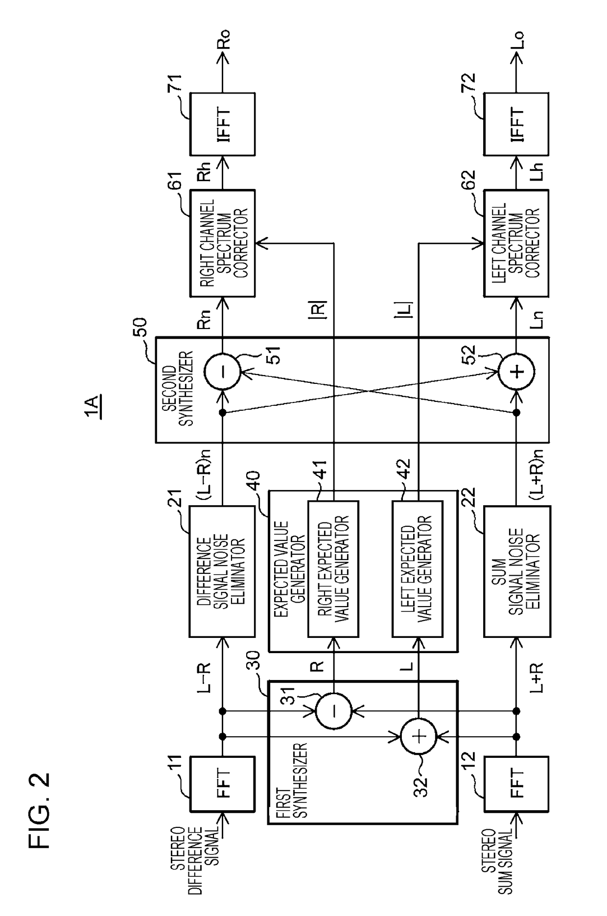
[0121]FIG. 2 is a block diagram showing an example of a configuration of a stereo reproduction apparatus 1A according to Embodiment 2 of the present disclosure. In comparison with the stereo reproduction apparatus 1, the stereo reproduction apparatus 1A further includes a sum signal noise eliminator 22. The sum signal noise eliminator 22 eliminates a noise component from the stereo sum signal L+R. As shown in FIG. 8, in the bandwidth of the stereo sum signal L+R (i.e. a bandwidth of up to 15 kHz), the noise spectrum according to the receiving electric-field strength S can be grasped in advance.

[0122]Accordingly, as with the difference signal noise eliminator 21, the sum signal noise eliminator 22 includes a noise map storing the noise spectrum according to the receiving electric-field strength S in advance therein and uses this noise map to estimate the noise spectrum. Moreover, the sum signal noise eliminator 22 eliminates the noise component from the stereo sum signal L+R by subtr...

embodiment 3

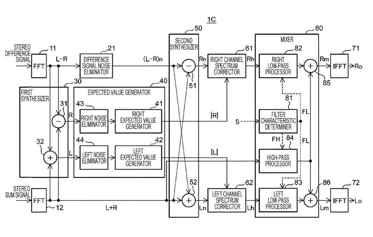
[0127]FIG. 3 is a block diagram showing an example of a configuration of a stereo reproduction apparatus 1B according to Embodiment 3 of the present disclosure. The stereo reproduction apparatus 1B includes an expected value generator 40 which is difference in configuration from that of the stereo reproduction apparatus 1.

[0128]That is, the expected value generator 40 further includes a right noise eliminator 43 and a left noise eliminator 44. The right noise eliminator 43 eliminates a noise component from the right channel spectrum R outputted from the first synthesizer 30. The left noise eliminator 44 eliminates a noise component from the left channel spectrum L outputted from the first synthesizer 30.

[0129]Note here that the right and left noise eliminators 43 and 44 eliminate the noise components by a second noise suppression amount that is smaller than a first noise suppression amount that is the noise suppression amount of the difference signal noise eliminator 21. Such a pred...


PUM


Abstract

A right expected value generator generates an expected value of a right channel spectrum from the right channel spectrum. Further, a left expected value generator generates an expected value of a left channel spectrum from the left channel spectrum. Further, a right channel spectrum corrector so corrects a right channel spectrum outputted from a second synthesizer that the right channel spectrum does not exceed the expected value of the right channel spectrum. Moreover, a left channel spectrum corrector so corrects a left channel spectrum outputted from the second synthesizer that the left channel spectrum does not exceed the expected value of the left channel spectrum.

Description

BACKGROUND1. Technical Field[0001]The present disclosure relates to a stereo reproduction apparatus in an FM stereo receiver.2. Description of the Related Art[0002]In extracting a left channel signal and a right channel signal from a stereo sum signal and a stereo difference signal in a stereo reproduction apparatus, it is desirable to reduce noise while maintaining stereo balance between the signals. To this end, Japanese Unexamined Patent Application Publication No. 2014-146942 discloses a technique for estimating noise components contained in a stereo sum signal and a stereo difference signal, respectively, eliminating, from the stereo sum signal and the stereo difference signal, the noise components thus estimated, and generating left and right channel signals from the stereo sum signal and the stereo difference signal from which the noise components have been eliminated.[0003]Japanese Unexamined Patent Application Publication No. 2014-146942 employs non-linear processing such a...

Claims


Application Information

Patent Timeline
Patent Type & Authority Patents(United States)
IPC IPC(8): H04H40/72H04S1/00
CPCH04S1/002H04H40/72H04S2420/07H04S1/00H04S7/30H04B1/1646H04H40/63
Inventor FURUKAWA, HIROKI
Owner PANASONIC INTELLECTUAL PROPERTY CORP OF AMERICA
Why Eureka
Try Eureka