Method and system for automatically inscribing noisy objects in scanned image data within a minimum area rectangle

Inactive Publication Date: 2006-04-06
MICROSOFT TECH LICENSING LLC
View PDF25 Cites 18 Cited by
  • Summary
  • Abstract
  • Description
  • Claims
  • Application Information

AI Technical Summary

Benefits of technology

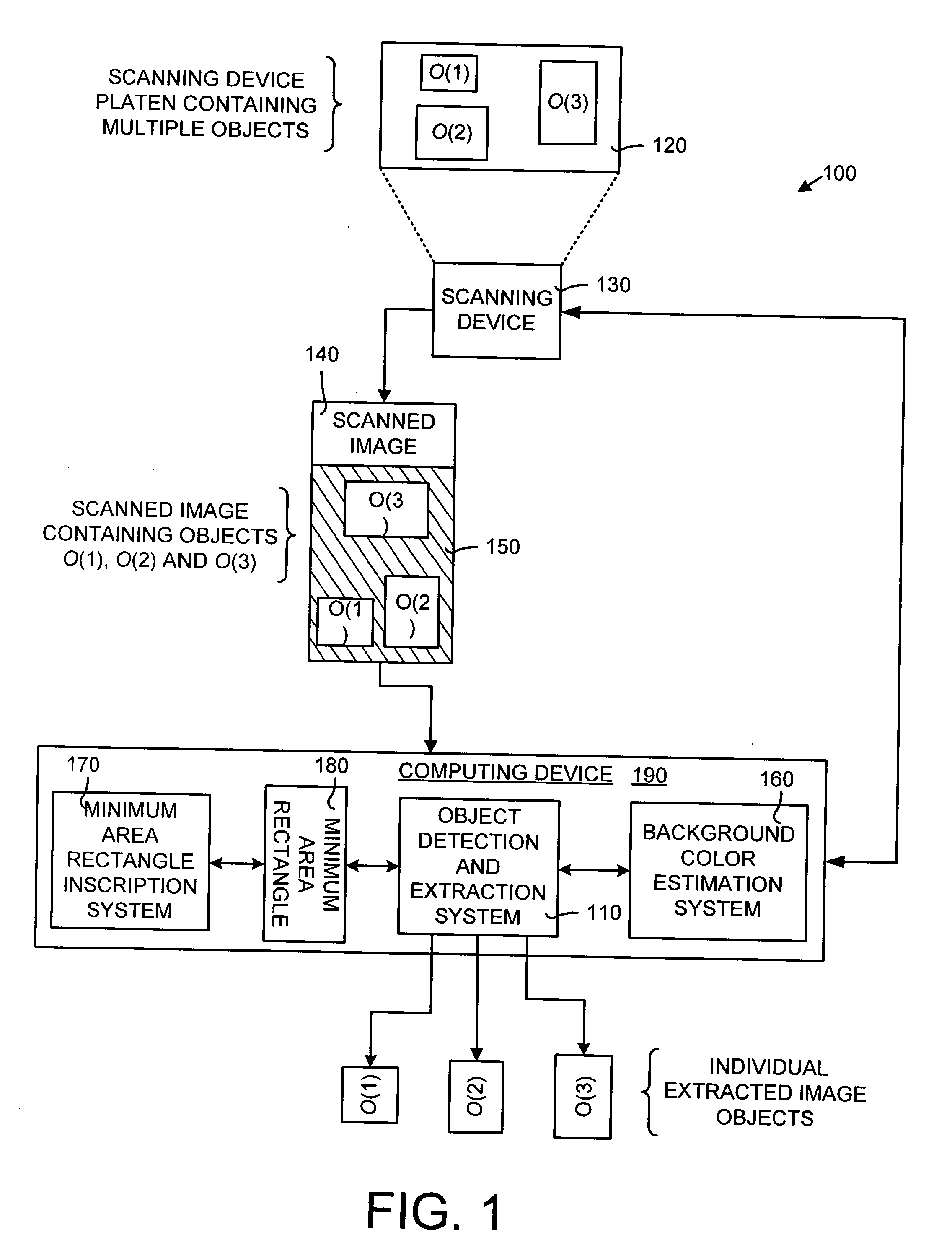
[0006] The invention disclosed herein includes a minimum area rectangle inscription method and system for automatically finding a minimum area rectangle that circumscribes a noisy object in scanned image data. The method and system are simple and efficient and can accurately and robustly determine a minimum area rectangle that inscribes a noisy object located in scanned image data. The minimum area rectangle inscription method and system alleviates the need for a user to manually draw bounding rectangles around a noisy object. Moreover, the minimum area rectangle inscription method and system aids any detection and extraction technique by providing such a technique with an accurate bounding rectangle for each object in scanned image data.

Problems solved by technology

However, this can be a particularly laborious task for a user, since current techniques require the user to manually draw a bounding rectangle around each object before the object can be detected and extracted.
This process of manually drawing bounding rectangles is even more difficult when the objects are “noisy”.
In many image processing algorithms, the complexity and time to process of the algorithm also quadruples.
This spares the user the time and effort of performing manual segregation of each object.
A noisy object is an object that is deformed such that it is no longer perfectly rectangular and lack well-defined edges and corners.

Method used


Image

  • Method and system for automatically inscribing noisy objects in scanned image data within a minimum area rectangle
  • Method and system for automatically inscribing noisy objects in scanned image data within a minimum area rectangle
  • Method and system for automatically inscribing noisy objects in scanned image data within a minimum area rectangle

Examples


working examples

VI. WORKING EXAMPLES

[0076] In order to more fully understand the minimum area rectangle inscription system and method disclosed herein, the operational details of two exemplary working examples are presented. It should be noted that these working examples are only two ways in which the minimum area rectangle inscription system and method may be implemented.

first working example

[0077]FIGS. 5A-5H illustrates a first working example using the minimum area rectangle inscription method shown in FIGS. 3 and 4. FIG. 5A illustrates a first object 500 that is not perfectly rectangular that is used in this first working example. It should be noted that for the sake of simplicity only a single object is shown. Moreover, the remainder of the scanned image data is not shown. However, it should be realized that the first object 500 is contained in scanned image data. Moreover, the first object may be one of several objects contained in the scanned image data.

[0078] Initially, a first interior point 510 is found within the first object 500. Any number of interior points may be used, but for simplicity, only a single interior point is shown and used in this first working example. As noted above, the first interior point may be found using a variety of techniques. In this first working example, the centroid or center of mass of the first object 500 was found to determine...

second working example

[0093]FIGS. 7A-7I illustrate a second working example using the minimum area rectangle inscription method shown in FIGS. 3 and 4. In this second working example, not all of the perimeter points are used to construct a convex hull, since one of the perimeter points causes a concave side. This is described in greater detail below.

[0094]FIG. 7A illustrates a second object 700 that is not perfectly rectangular (i.e., a noisy object) used in this second working example. Again, for the sake of simplicity, only a single object is shown, and the remainder of the scanned image data is not shown.

[0095]FIG. 7B illustrates selecting a second interior point 710 within the second object 700. Any number of interior points may be used, but in this second working example, only a single interior point was used. The second interior point 710 was found by calculating the center of mass of the second object 700. Alternatively, any number of existing methods could be used to find a point that is locate...


PUM


Abstract

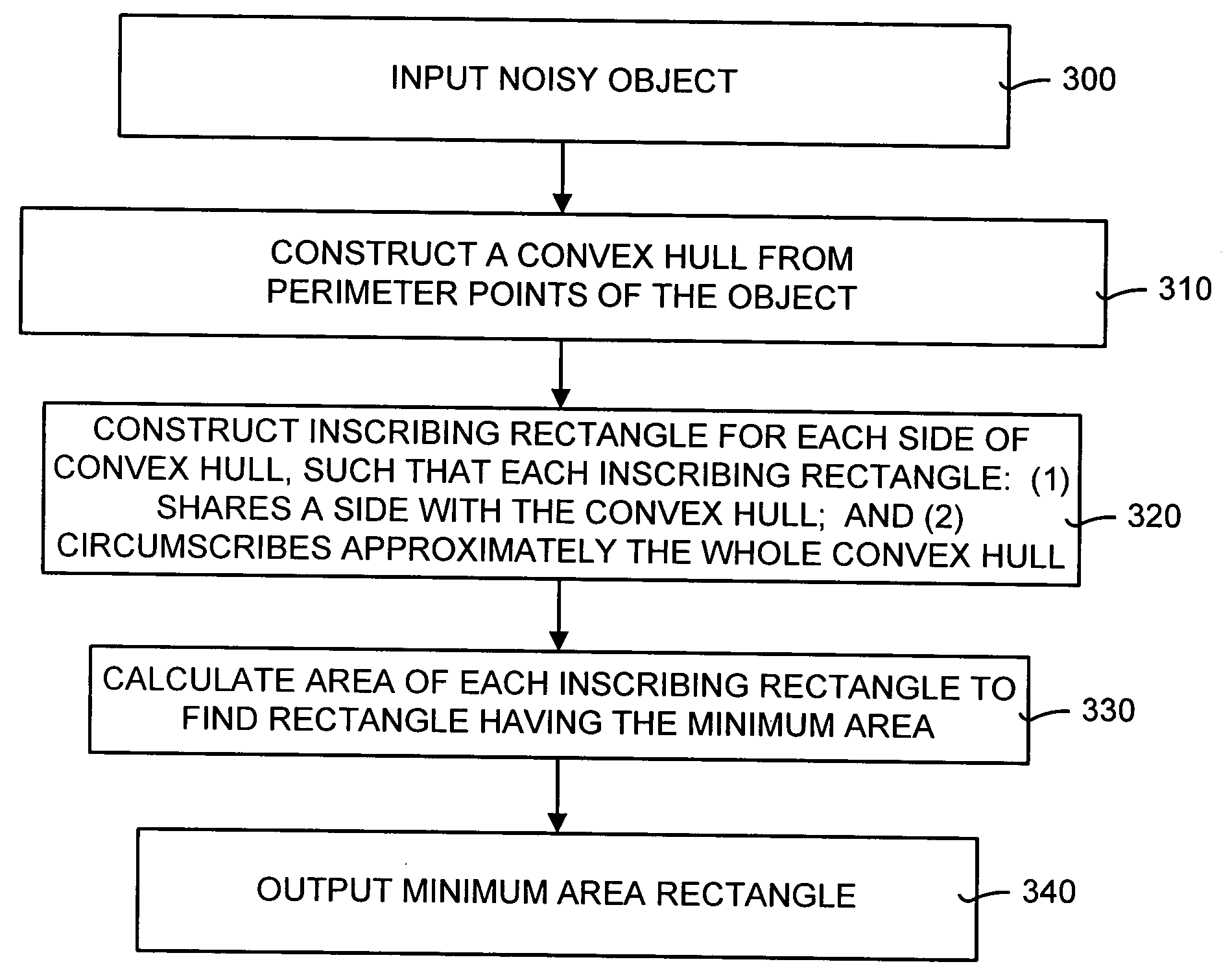
A minimum area rectangle inscription method and system for automatically generating a minimum area rectangle that inscribes and bounds an approximately rectangular object (or “noisy” object) contained within scanned image data. The minimum area rectangle inscription method chooses an interior point located inside the object boundary and determine perimeter points located on the boundary. A convex hull is constructed from at least some of the perimeter points such that each side of the convex hull is convex. Inscribing rectangles, equal in number to the sides of the convex hull, are constructed such that each inscribing rectangle shares a side with the convex hull and circumscribes approximately the entire convex hull. The area of each of the inscribing rectangles is calculated, and the inscribing rectangle having the least amount of area is designated as the minimum area rectangle.

Description

TECHNICAL FIELD [0001] The present invention relates in general to image processing of digital image data and more particularly to a minimum area rectangle inscription system and method for automatically generating a minimum area rectangle that inscribes and bounds an approximately rectangular object (or “noisy” object) contained within scanned image data. BACKGROUND OF THE INVENTION [0002] Optical scanners are popular and useful peripheral devices for computers. Optical scanners are used to take objects containing printed information (such as text, illustrations or photographs) and convert the information into a digital form that a computer can use. In general, a user places objects to be scanned onto a platen of the scanner. A scanner head is passed over the platen area and the resultant image is divided into a plurality of pixels. Each pixel location is assigned a value that is dependent on the color of the pixel. The resulting matrix of bits (called a bit map) can then be stored...

Claims


Application Information

Patent Timeline
IPC IPC(8): G06K9/34
CPCG06T7/0083G06T2207/10008G06T2207/30176G06T7/12
Inventor HERLEY, CORMAC E.
Owner MICROSOFT TECH LICENSING LLC
Why Eureka
Try Eureka