Gas turbine airfoil film cooling hole
- Summary
- Abstract
- Description
- Claims
- Application Information
AI Technical Summary
Benefits of technology
Problems solved by technology
Method used
Image

Examples
Embodiment Construction
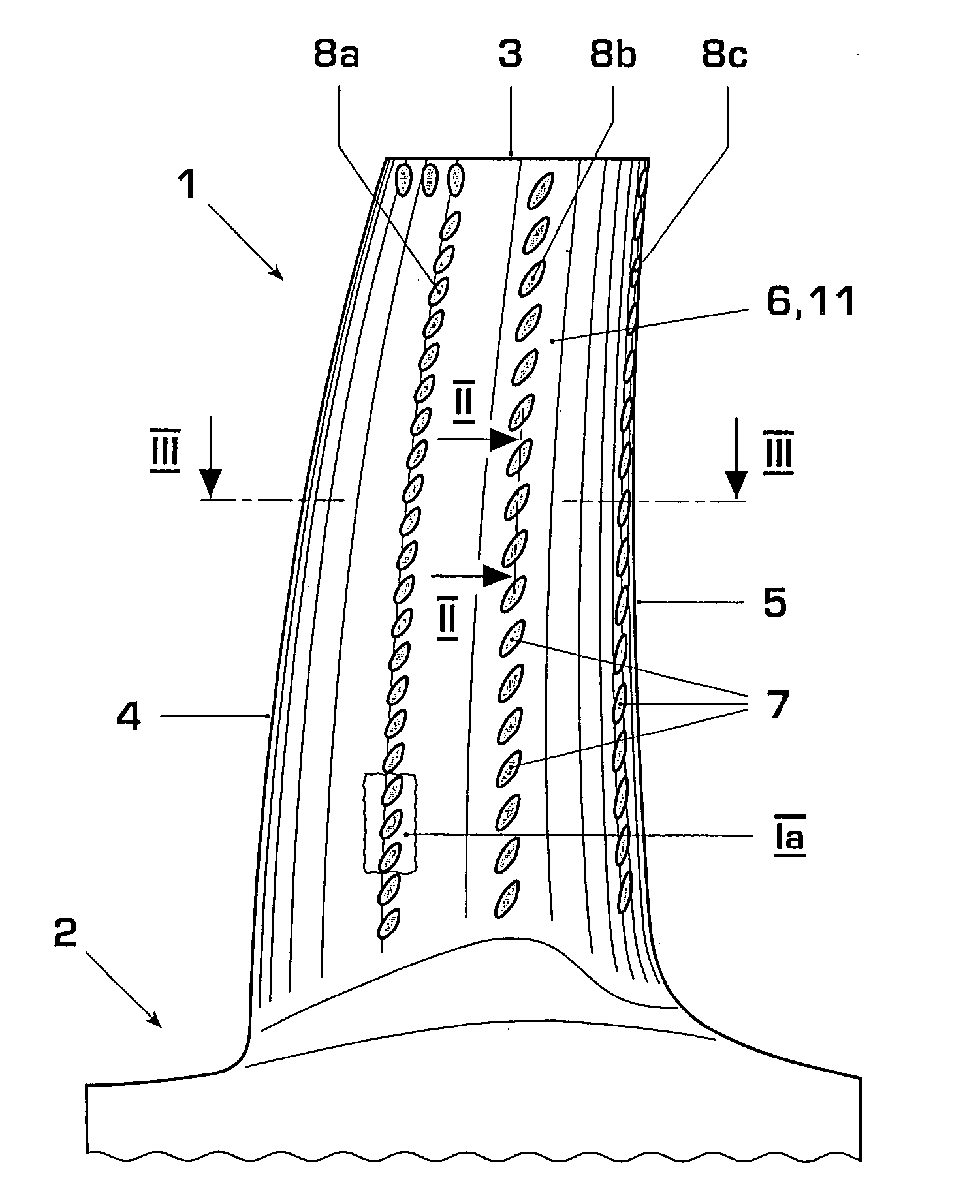
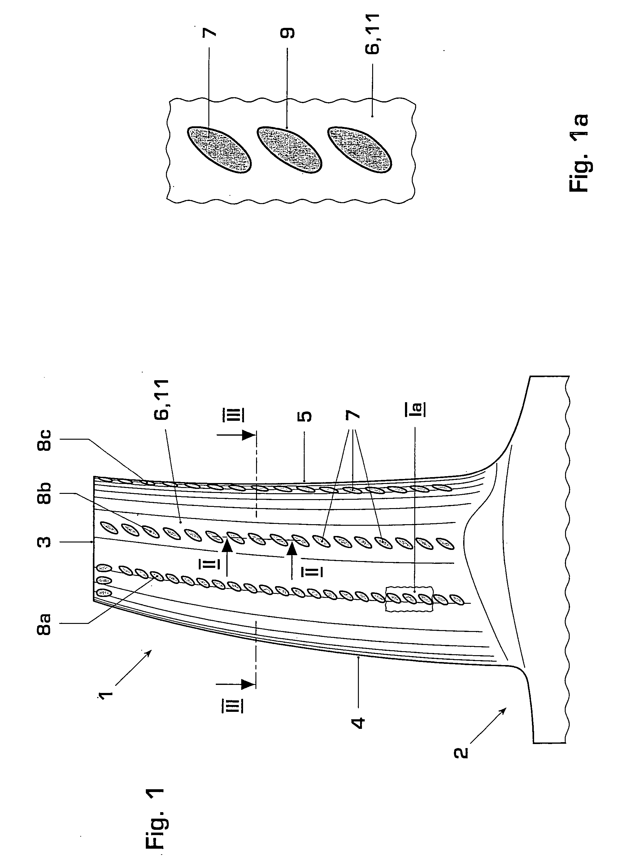
[0023]FIG. 1 shows a typical airfoil 1 of a gas turbine extending from a root 2 to a tip 3 and frown a leading edge 4 to a trailing edge 5. The figure shows the airfoil from its suction side 6. Several film cooling holes 7 are arranged In radially extending rows 8a, 8b, and 8c on the suction side 6. The film cooling holes 7 are realized with diffused sidewalls resulting in an irregularly shaped exit port 9 as shown in an enlarged view in FIG. 1a.
[0024] The film cooling holes extend from internal cooling passages within the airfoil 1 through the suction sidewall 6 to its outer surface 11. They provide convective cooling of the sidewall from within as well as film cooling of the sidewall outer surface 11.
[0025] In one embodiment of the invention the film cooling holes with diffused sidewalls are arranged in one or more radially extending rows on the suction side of the airfoil.
[0026] The number of rows of film cooling holes and their position is determined based on the metal temper...
PUM
 Abstract
Description
Claims
Application Information
 - R&D
- Intellectual Property
- Life Sciences
- Materials
- Tech Scout
- Unparalleled Data Quality
- Higher Quality Content
- 60% Fewer Hallucinations
Browse by: Latest US Patents, China's latest patents, Technical Efficacy Thesaurus, Application Domain, Technology Topic, Popular Technical Reports.
© 2025 PatSnap. All rights reserved.Legal|Privacy policy|Modern Slavery Act Transparency Statement|Sitemap|About US| Contact US: help@patsnap.com