Drywall sander

a drywall sander and drywall technology, applied in the direction of gear teeth, manufacturing tools, manufacturing apparatuses for gear teeth, etc., can solve the problems of user fatigue and time-consuming, the speed in which the compound may be removed, and the difficulty of removing the excess joint compound,

Active Publication Date: 2006-04-06
BLACK & DECKER INC
View PDF11 Cites 41 Cited by
  • Summary
  • Abstract
  • Description
  • Claims
  • Application Information

AI Technical Summary

Benefits of technology

[0009] In a first aspect of the present invention, a sander including a power unit is disclosed. The power unit includes a motor for supplying rotational torque to the sander. A sanding assembly is operationally coupled to the power unit. A telescopic support arm assembly is coupled to the sanding assembly and the power unit for supporting the sanding assembly. The telescopic support arm assembly includes a first support arm with a first and a se

Problems solved by technology

It is the removal of the excess joint compound that is often difficult as well as tedious.
However, use of a non-motorized sander often led to user fatigue and was very time consuming.
Although currently available motorized drywall sanders have increased the speed in which the compound may be removed, such sanders are limited.
First, the amount of time required to complete a sanding job may be actually increased when using such sanders when compared to a non-motorized sander.
For example, while the speed of compound removal is increased

Method used


Image

  • Drywall sander
  • Drywall sander
  • Drywall sander

Examples


Embodiment Construction

[0027] Reference will now be made in detail to the presently preferred embodiments of the invention, examples of which are illustrated in the accompanying drawings.

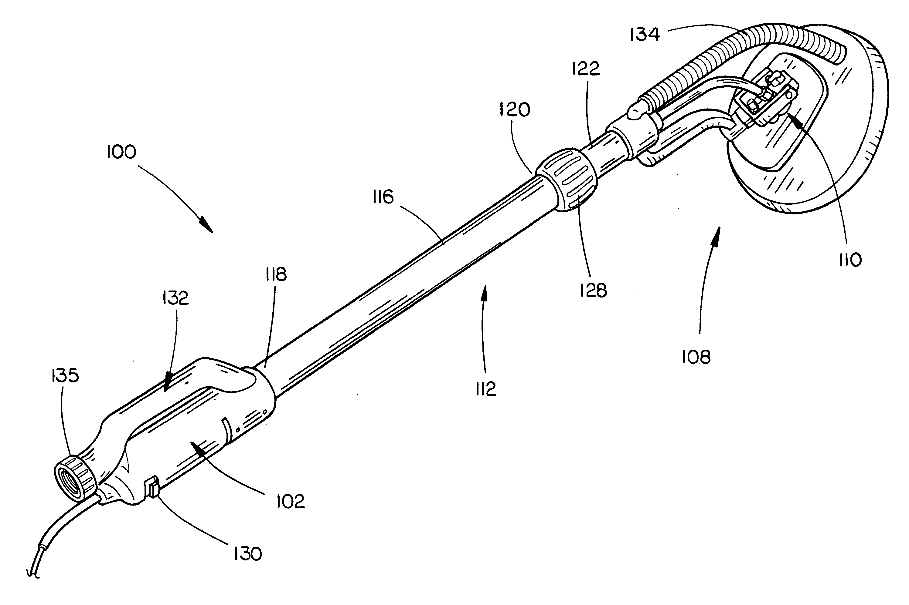
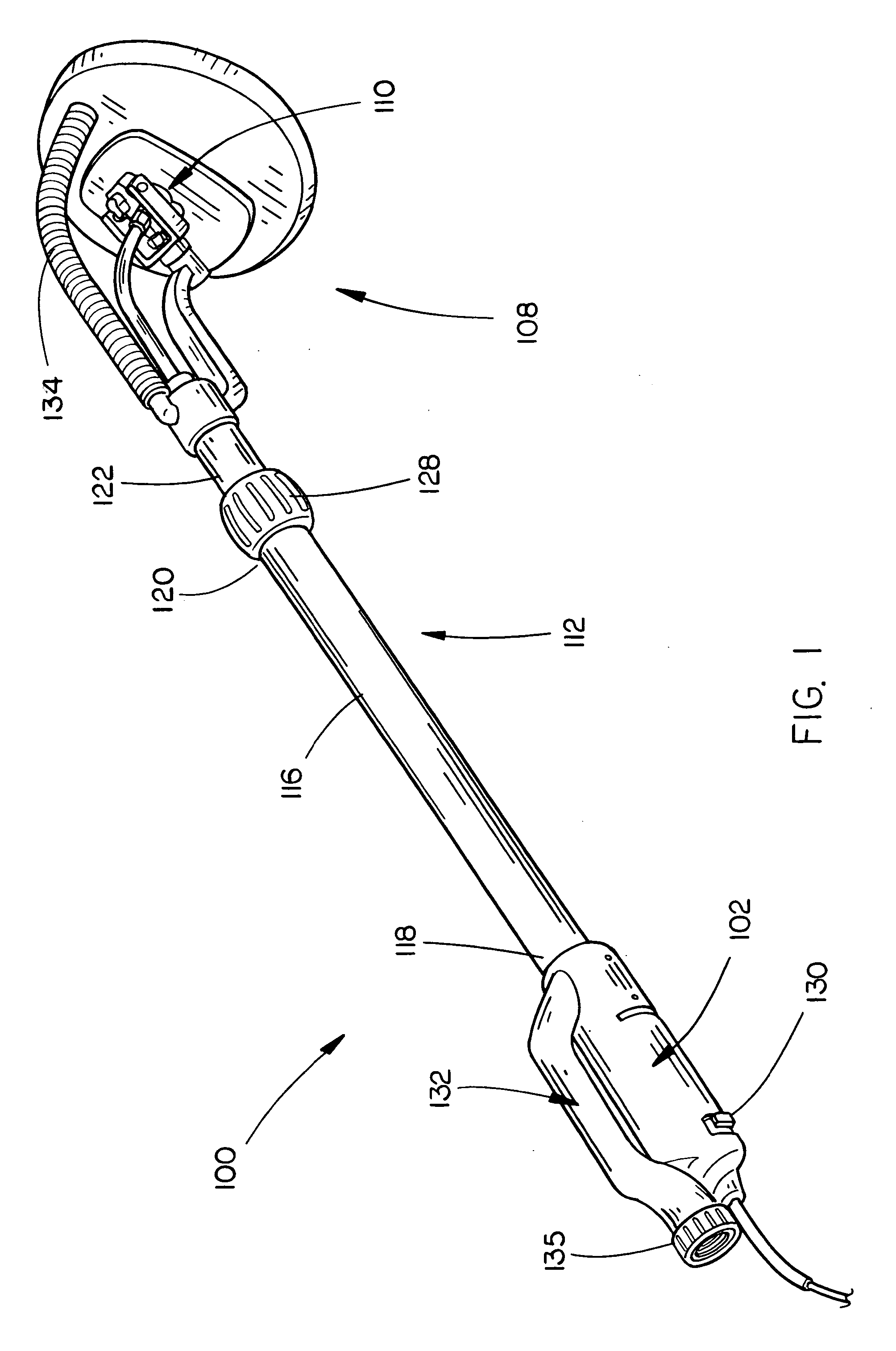
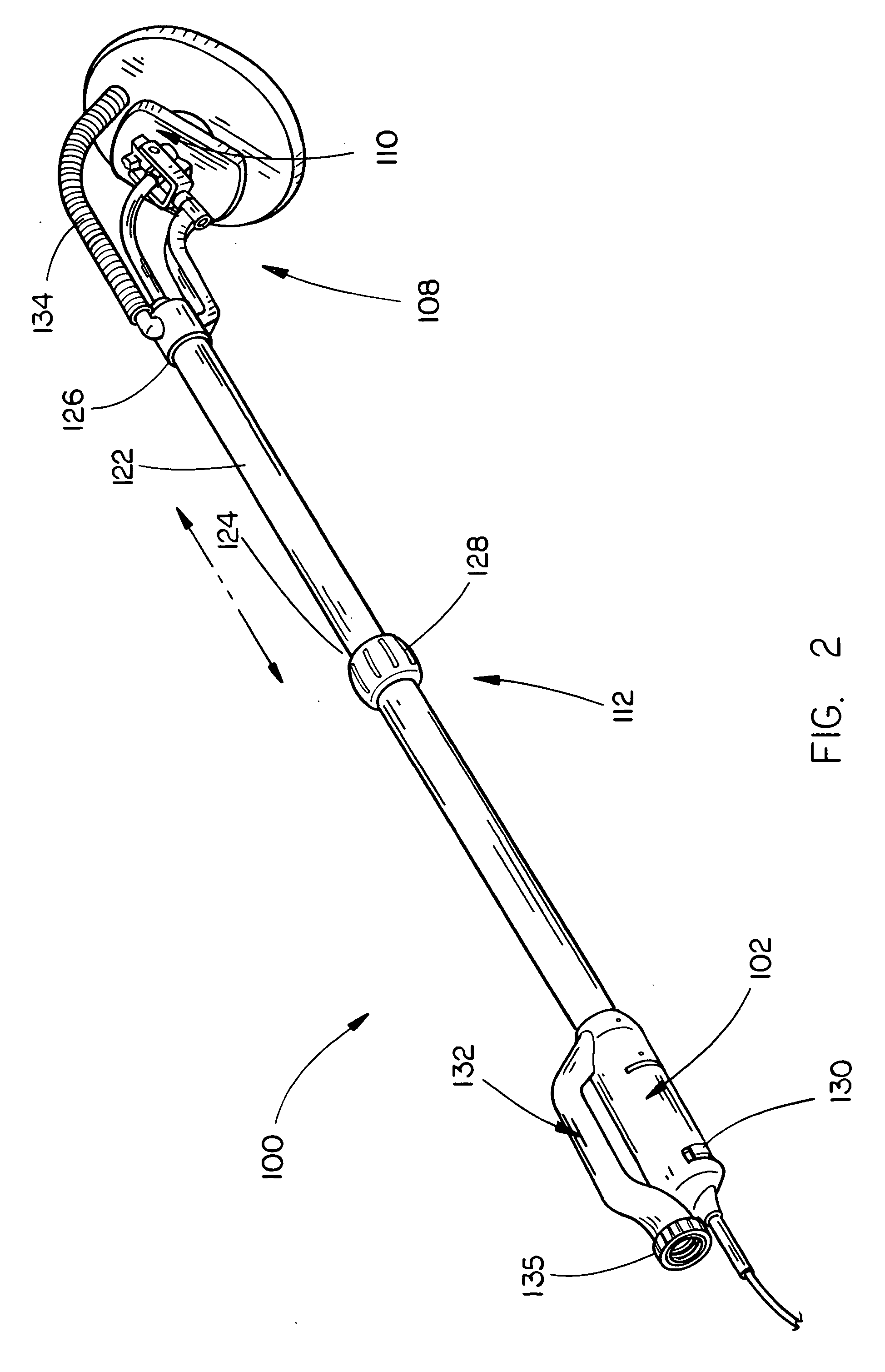
[0028] Referring in general to FIGS. 1 through 11, a drywall sander including a telescopic support arm assembly and the capability of receiving variously shaped interchangeable sanding heads and providing different motions is provided. Conventional drywall sanders include a rotational pad head capable of rotating at a single speed (e.g. two thousand revolutions per minute, 2000 rpm). Although such sanding head works well for most areas of a wall, access into corners or edges is often limited. For example, a user might not be able to access the corners or edges of a wall easily, causing such surface to be uneven when compared to the surrounding area. In addition, a user may need to sand a portion of the ceiling as well as an area relatively close to the ground surface. The present invention provides a sander which include...


PUM


Abstract

The present invention provides an adjustable drywall sander capable of imparting more than one type of motion. In an exemplary embodiment, the sander includes a power unit with a motor and a sanding assembly coupled to the power unit. A telescopic support arm assembly is coupled to the sanding assembly and the power unit for supporting the sanding assembly. The telescopic support arm assembly includes a first support arm with a first and a second end and a second support arm with a first and second end. The first end of the first support arm being coupled to the power unit and the second end of the second support arm being coupled to the sanding assembly. A collapsible drive shaft is substantially enclosed by the telescopic support arm assembly. The telescopic support arm assembly and the collapsible drive shaft allow the length of the telescopic assembly to be adjusted.

Description

CROSS REFERENCE TO RELATED APPLICATIONS [0001] The present application claims the benefit under 35 U.S.C. § 119(e) of U.S. Provisional Patent Application Ser. No. 60 / 614,189, entitled “Drywall Sander,” filed Sep. 29, 2004 and U.S. Provisional Patent Application Ser. No. 60 / 643,058, entitled “Drywall Sander with Interchangeable Heads,” filed Jan. 11, 2005 both of which are herein incorporated by reference in their entireties.FIELD OF INVENTION [0002] The present invention generally relates to the field of power tools, and more particularly to a device for sanding drywall. BACKGROUND OF THE INVENTION [0003] In order for the joints between drywall panels to disappear so that the walls and ceilings are smooth, a compound known as joint compound is employed. First, joint compound is applied over the joints in excess and allowed to dry. Second, the excess compound is removed by a sander. It is the removal of the excess joint compound that is often difficult as well as tedious. [0004] Trad...

Claims


Application Information

Patent Timeline
IPC IPC(8): B24B23/00
CPCB24B7/184B24B55/10B24B47/12
Inventor PHILLIPS, ALANSCHNELL, JOHN W.WALL, DANIEL PAXTON
Owner BLACK & DECKER INC
Why Eureka
Try Eureka