Techniques for inductive communication systems

a communication system and inductive technology, applied in the field of inductive communication system techniques, can solve problems such as annoyance or even detrimental effects

Inactive Publication Date: 2006-04-06
FREELINC HLDG LLC
View PDF6 Cites 40 Cited by
  • Summary
  • Abstract
  • Description
  • Claims
  • Application Information

AI Technical Summary

Benefits of technology

[0020] In one instance, a base transceiver device is used in a cellular phone and a remote transceiver device is used in to a headset including a speaker and a microphone. Based on use of a communication code and bidirectional communications between the transceiver devices, a user can communicate over an exclusive inductive link between the cell phone and headset. A user wearing the headset can therefore communicate with a remote party through a phone link supported by the cell phone. The transceiver devices can include multiple transducers so that continuous communication between the headset and cell phone can be maintained regardless of the orientation and position of the transceiver devices.

Problems solved by technology

This can be annoying or even detrimental if the communication was intended to be confidential.
Thus, unique problems arise when multiple transceiver devices attempt to share an available bandwidth to communicate with each other.

Method used


Image

  • Techniques for inductive communication systems
  • Techniques for inductive communication systems
  • Techniques for inductive communication systems

Examples


Embodiment Construction

[0049] A description of preferred embodiments of the invention follows.

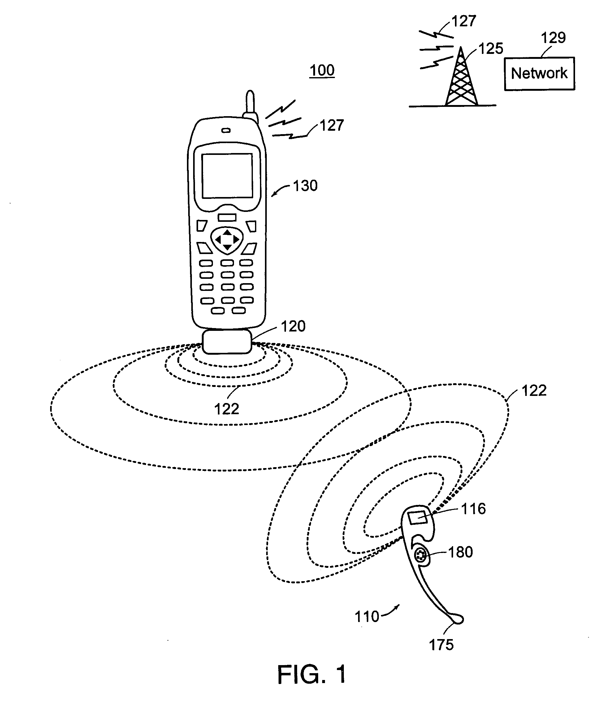
[0050]FIG. 1 is a pictorial diagram of a wireless communication system according to certain principles of the present invention. As shown, wireless communication system 100 includes cellular phone device 130 and headset 110. Generally, headset 110 is worn by a user to communicate with a remote party over one or multiple wireless links. For example, inductive link 122 supports communications between a user wearing headset 110 and cell phone 130. Radio Frequency (RF) link 127 supports communications between cell phone 130 and cellular base station 125. Base station 125 is coupled to network 129 such as a PSTN (Public Switching Telephone Network).

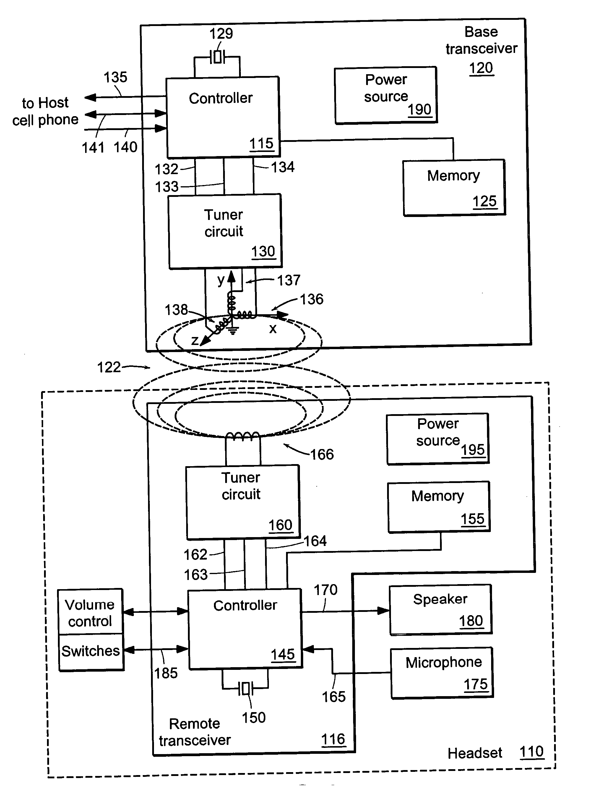
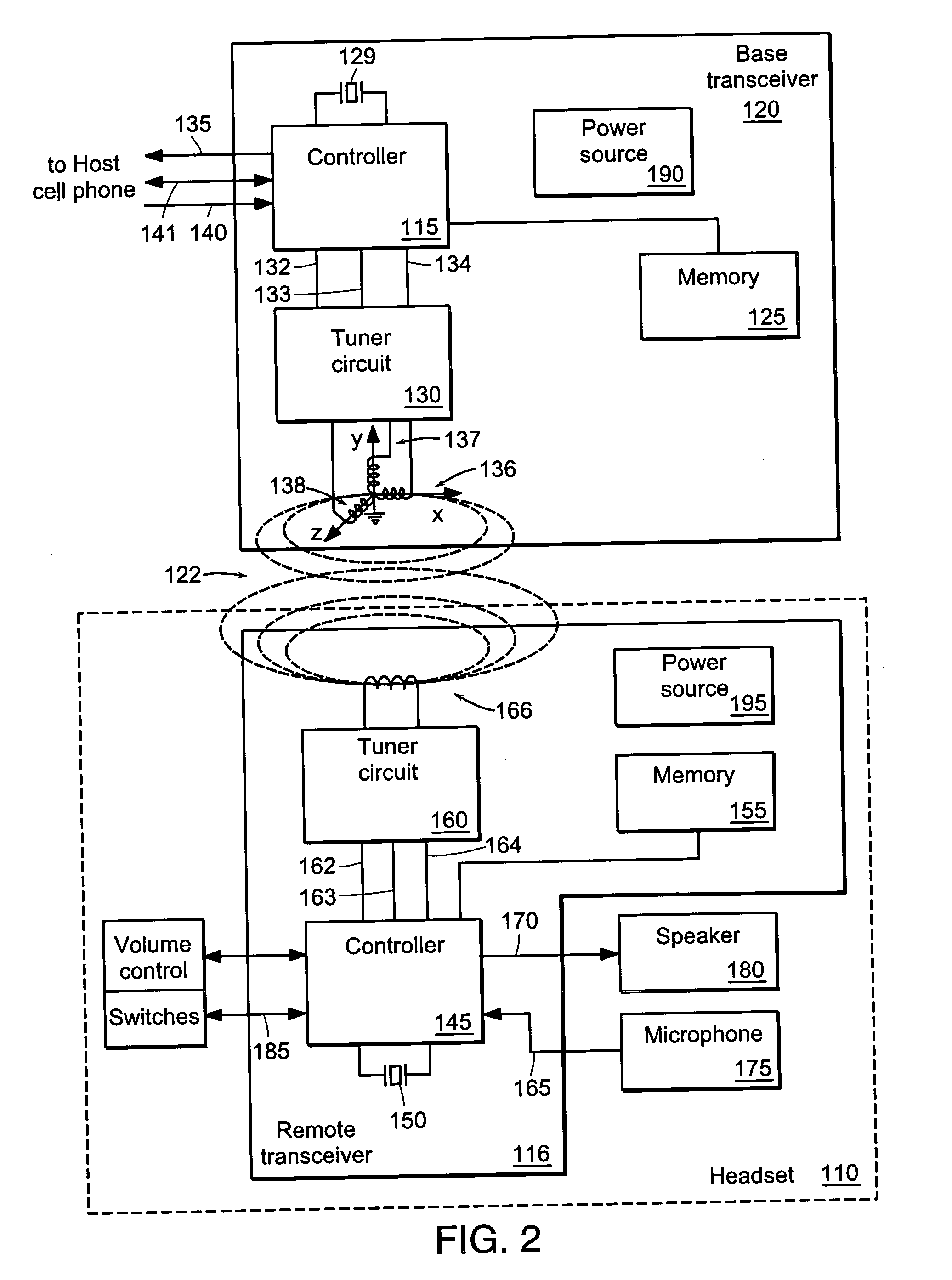
[0051] Instead of holding cell phone 130 to one=s ear as is ordinarily done to communicate over a telephone with a remote party, a user wearing headset 110 can communicate with the party using headset 110. For example, a user can speak into microphone 112 to convey a voic...


PUM


Abstract

Contents of one or more received messages can be analyzed to determine whether a transceiver device generating the inductive field has already been programmed with a unique communication code. If not, bidirectional communications can be established to program the transceiver device with a unique communication code over an inductive link. Orientation or position of a transceiver device can be used to initiate a process for programming a communication code. Generally, the communication code can define a unique relationship between two or more transceiver devices.

Description

RELATED APPLICATION(S) [0001] This application is a divisional of U.S. application Ser. No. 10 / 100,229, filed Mar. 15, 2002, which is a continuation-in-part of U.S. application Ser. No. 10.004,989 filed Dec. 3, 2001 and U.S. application Ser. No. 09 / 942,372 filed Aug. 29, 2001, and claims the benefit of U.S. Provisional Application No. 60 / 301,529 filed on Jun. 28, 2001, U.S. Provisional Application No. 60 / 296,229 filed Jun. 6, 2001 and U.S. Provisional Application No. 60 / 276,398 filed on Mar. 16, 2001. The entire teachings of the above applications are incorporated herein by reference.BACKGROUND OF THE INVENTION [0002] Transducers have been incorporated in transceivers to transmit and receive inductive fields. In a typical application, each of two transceiver devices supporting bidirectional communication includes two specifically tuned transducers, one of which is tuned for transmitting while the other is tuned for receiving. [0003] Interference can occur among transceiver devices w...

Claims


Application Information

Patent Timeline
Patent Type & Authority Applications(United States)
IPC IPC(8): H04Q7/20H04B5/02H04B5/06H04B7/02H04M1/60H04M1/727H04M1/737
CPCH04B5/02H04B5/06H04B7/02H04B7/022H04M1/6066H04M1/727H04M1/737H04R2420/07
Inventor PALERMO, VINCENTMARSHALL, CHARLES M.WHITE, TIMOTHY E.VOEGELIN, STEPHEN A.LAFRANCHISE, JEFFREY R.
Owner FREELINC HLDG LLC
Why Eureka
Try Eureka