Combination of body and striking plate for golf club head

Inactive Publication Date: 2006-04-06
NELSON PRECISION CASTING
View PDF5 Cites 20 Cited by
  • Summary
  • Abstract
  • Description
  • Claims
  • Application Information

AI Technical Summary

Benefits of technology

[0006] An object of the present invention is to provide a golf club head including a

Problems solved by technology

The golf club head cannot

Method used


Image

  • Combination of body and striking plate for golf club head
  • Combination of body and striking plate for golf club head
  • Combination of body and striking plate for golf club head

Examples


first embodiment

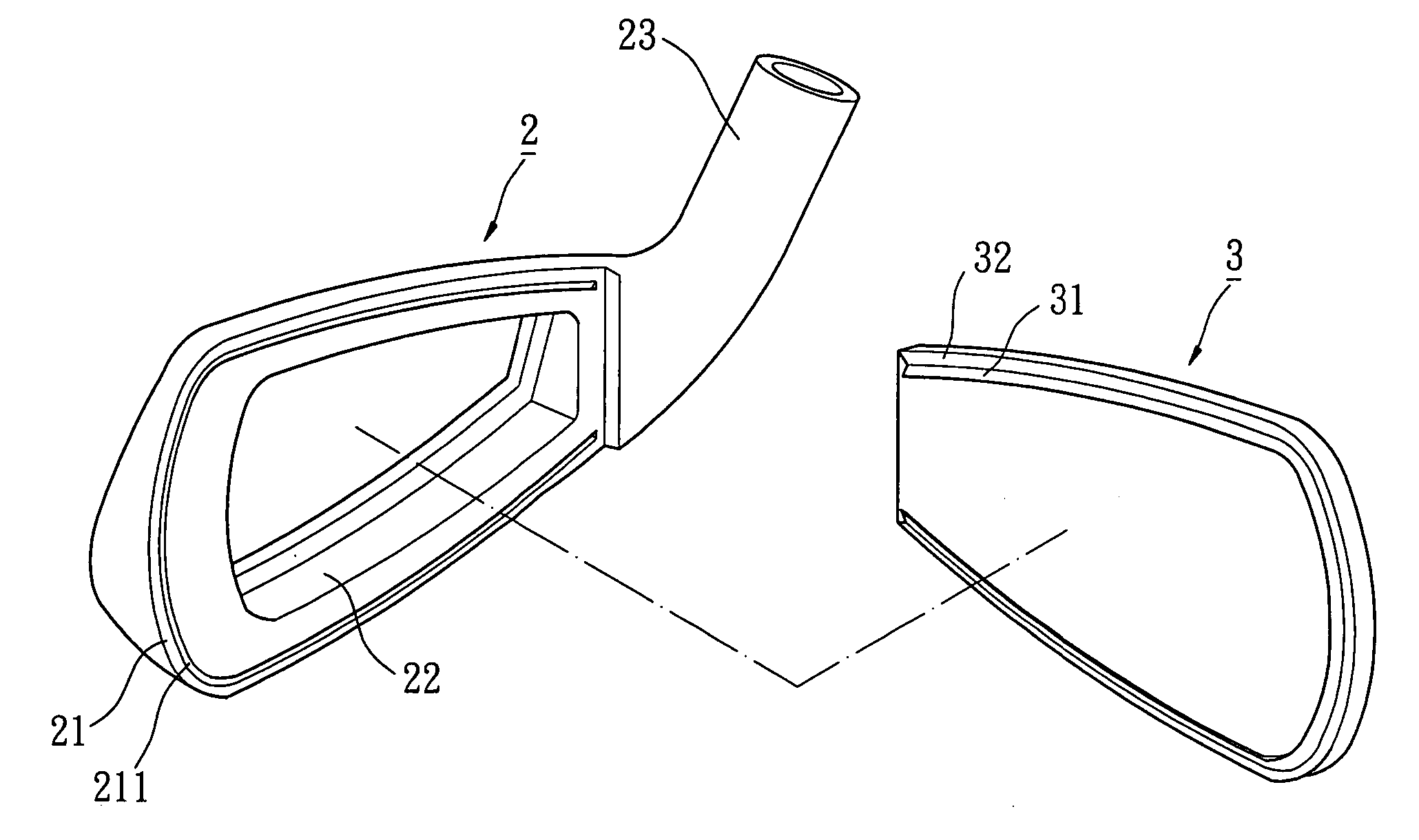
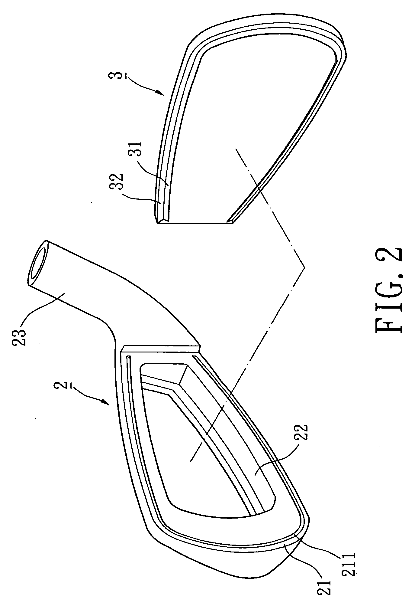
[0031] Referring to FIGS. 2 and 3, a golf club head in accordance with the present invention comprises a body 2 and a striking plate 3. The body 2 is made of a metal material with a relatively higher rigidity, such as stainless steel, low-carbon steel, or alloy steel. The body 2 includes a front side in which a recessed portion 22 is defined, with an engaging face 21 surrounding a front opening of the recessed portion 22. A substantially slantingly V-shaped groove 211 is defined in the engaging face 21. The V-shaped groove 211 is adjacent to and extends along the outer perimeter of the body 2. The V-shaped groove 211 inclines toward the recessed portion 22 or the outer perimeter of the body 2. The recessed portion 22 provides a buffering space for the striking plate 3 that deforms rearward when striking a golf ball. A hosel 23 is provided on a side of the body 2 (preferably a side of the recessed portion 22) for engaging with a shaft (not shown).

[0032] Still referring to FIGS. 2 and...

fifth embodiment

[0041]FIGS. 10 and 11 illustrate the invention. In this embodiment, the golf club head includes a body 4 and a striking plate 5. The body 4 includes a recessed portion 42, a positioning groove 41 surrounding the recessed portion 42, a positioning flange 43, a plastic protrusion 44, and an auxiliary plastic protrusion 45. A positioning flange 51, an engaging face 52, and a groove 53 are formed on a rear side of the striking plate 5.

[0042] In assembly, the positioning flange 51 of the striking plate 5 is engaged with the positioning groove 41, with the positioning flange 43 securely holding the positioning flange 51. A pointed section 441 of the plastic protrusion 44 of the body 4 abuts against a wall delimiting the groove 53. Next, the pointed section 441 of the plastic protrusion 44 deforms plastically and forms an engaging portion 44′ that is securely engaged in the groove 53. The auxiliary plastic protrusion 45 plastically deforms and forms a gap-filling portion, which is similar ...


PUM


Abstract

A golf club head includes a body and a striking plate. The body includes a front side having a recessed portion. The striking plate includes a front side for striking golf balls and a rear side. At least one groove is defined in one of the front side of the body and the rear side of the striking plate. At least one plastic protrusion is formed on the other of the front side of the body and the rear side of the striking plate. When assembling the striking plate and the body, the plastic protrusion deforms under pressure to form an engaging portion that is engaged in the groove, thereby securely engaging the striking plate with the body.

Description

BACKGROUND OF THE INVENTION [0001] 1. Field of the Invention [0002] The present invention relates to a golf club head. In particular, the present invention relates to a combination of a body and a striking plate for a golf club head. [0003] 2. Description of Related Art [0004]FIG. 1 illustrates a conventional golf club head comprising a body 11 and a striking plate 12. The body 11 includes a recessed portion 13 in a front side thereof. The recessed portion 13 includes an annular flange 14 and a shoulder 15 outside the annular flange 14. The striking plate 12 is substantially U-shaped in section and includes an annular abutting section 16. In assembly, the annular abutting section 16 of the striking plate 12 abuts against the shoulder 15 of the body 11 and engages with the annular flange 14. Then, welding is carried out to bond the annular abutting section 16 and the shoulder 15 together, forming a golf club head. [0005] The striking plate 12 and the body 11 must be manufactured with...

Claims


Application Information

Patent Timeline
IPC IPC(8): A63B53/04
CPCA63B53/04A63B2053/0416A63B53/0487A63B53/047A63B53/0466A63B53/0416A63B60/00
Inventor HSIEH, WEN-CHENGTSAI, JUNG-YAO
Owner NELSON PRECISION CASTING
Why Eureka
Try Eureka