Anti-backlash gear bearings

a gear bearing and anti-backlash technology, applied in the direction of toothed gearings, belts/chains/gearrings, toothed gearings, etc., can solve the problems of affecting the performance of the bearing, affecting the bearing performance, so as to improve the efficiency, strength and structural rigidity, and the effect of high mechanical advantag

Inactive Publication Date: 2006-04-06
NASA
View PDF7 Cites 14 Cited by
  • Summary
  • Abstract
  • Description
  • Claims
  • Application Information

AI Technical Summary

Benefits of technology

[0010] It is a further object of the present invention to provide a gear bearing system that results in a high mechanical advantage.
[0011] It is yet another object of the present invention to provide a gear bearing system that has improved efficiency, strength and structural rigidity.
[0012] It is still another object of the present invention to provide a gear bearing system that has a simpler construction and lower parts count.
[0013] It is another object of the present invention to provide a gear bearing system that is superior in bearing strength.
[0014] It is another object of the present invention to provide a gear bearing system in which it is easy to assemble, locate and stabilize gear systems.
[0015] It is still another object of the present invention to provide a gear bearing system common to both the electric motor drive in order to allow the armature and stator to function properly, and to provide a high mechanical advantage output.

Problems solved by technology

This arrangement takes up space and the interfaces make for a weaker system.
By using two, or even one separate bearing, separate interfaces require a separate attachment / detachment means which tends to rattle and is so flexible that the structure is weakened.
The pancake version is not as easy to lubricate and is not as efficient as the cup type, though they are more compact.
Both types are expensive and structurally weak, and the flexible splines tend to fail due to stripping.
While an anti-backlash feature is desirable to minimize “dead zones,” this system is unduly bulky, too complicated and very expensive to manufacture.

Method used


Image

  • Anti-backlash gear bearings
  • Anti-backlash gear bearings
  • Anti-backlash gear bearings

Examples


first embodiment

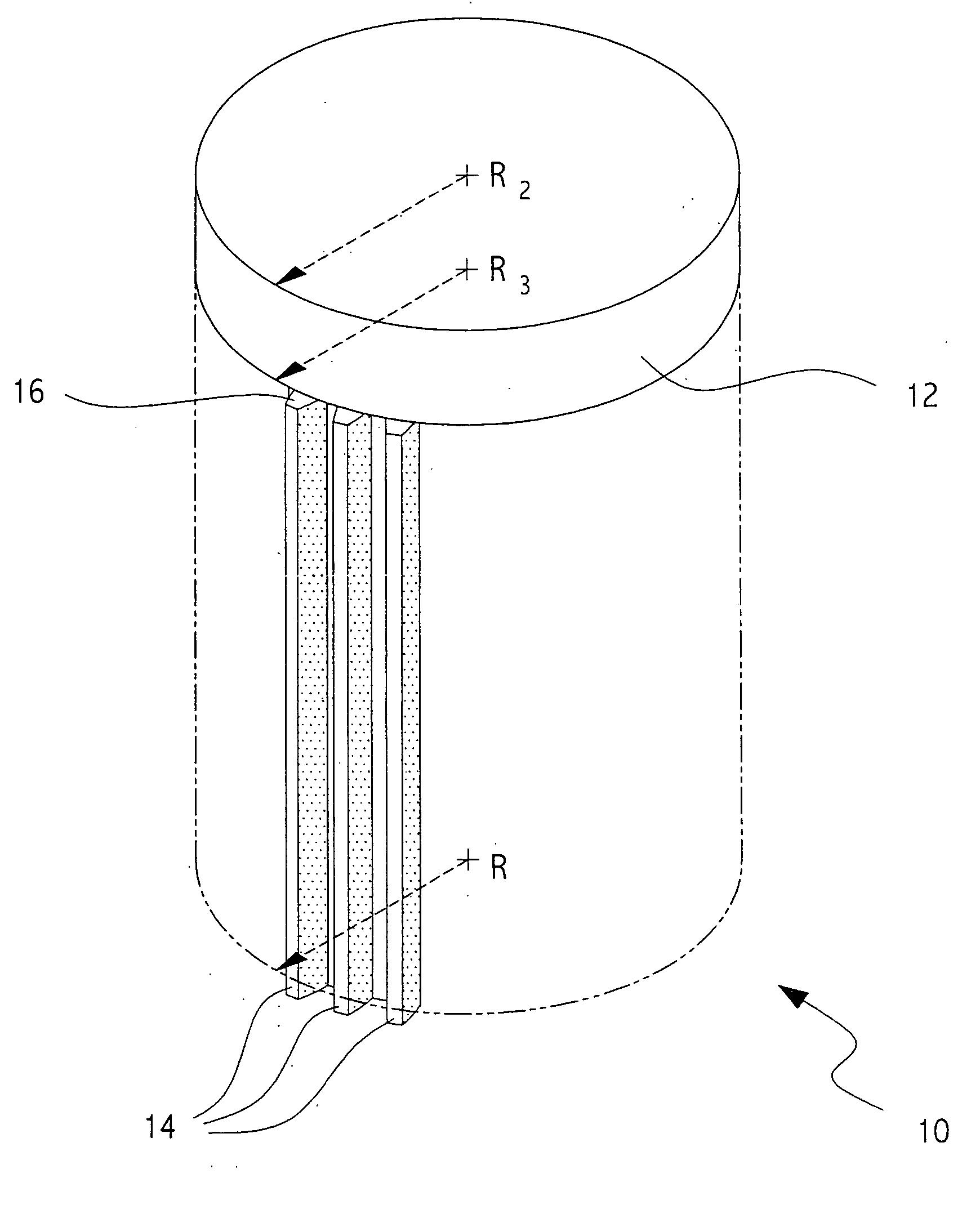
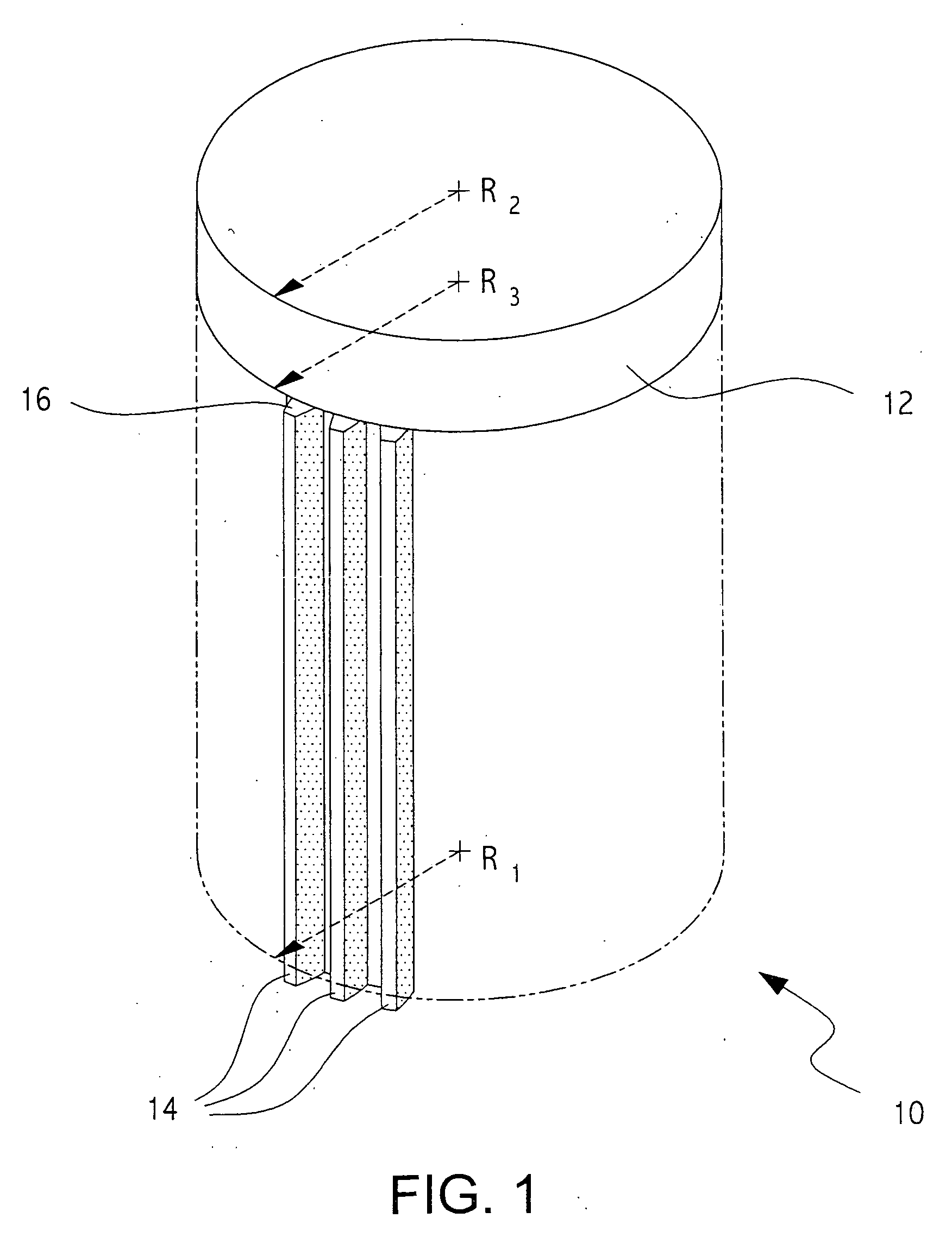
[0053] As illustrated in FIGS. 1, 2 and 3, the present invention relates to spur roller gear bearings. Referring to FIG. 1, spur roller gear bearings consist of a spur gear 10 which has a roller 12 coaxially mounted on its top. Spur gear teeth 14 extend radially from spur gear 10, and have a pitch radius R1. The radius of the roller R2 is substantially equal to the pitch radius R1 of the spur gear teeth. The tops of the spur gear teeth 14 form a crown 16. The radius to the crown top R3 is equal to the pitch radius and the roller radius. Since R1, R2 and R3 are substantially equal, the points at these radii move at substantially the same speed.

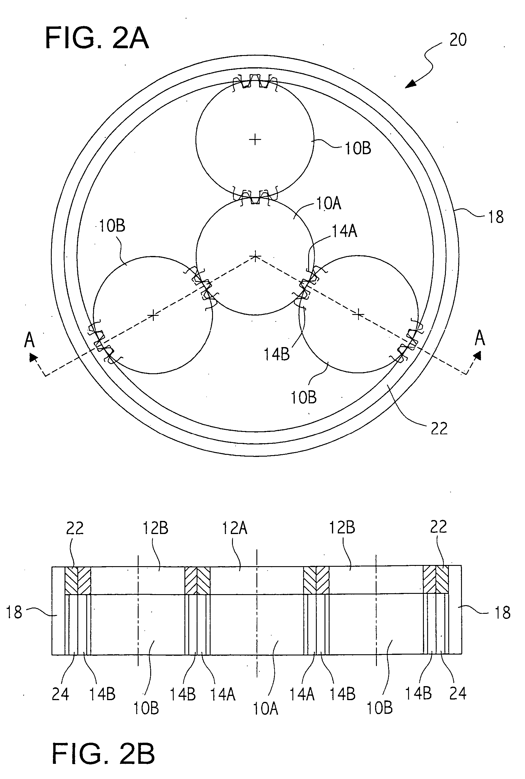
[0054] Referring now to FIG. 2A, we see that spur gears 10 can be configured with a ring gear 18 formed of ring gear teeth 24 to form planetary system 20. Planet spur gears 10B revolve around sun spur gear 10A. The spur gears 10A, B are shown here to be identical in size, however, one skilled in the art will recognize that sun spur 10A may be o...

second embodiment

[0058] Turning now to FIGS. 4, 5 and 6, we discuss the present invention, which involves phase-shifted gear bearings. FIG. 4 illustrates a phase-shifted spur gear 26 for use in phase-shifted gear bearings. Phase-shifted spur gear 26 includes an upper gear half 28 comprising upper gear teeth 30, and a lower gear half 32 comprising lower gear teeth 34. Upper gaps 36 and lower gaps 38 are formed between the gear teeth 32, 34. Upper gear half 28 is rotated with respect to lower gear half 32 so that the two halves are exactly out of phase with respect to each other. That is, upper gear teeth 30 are positioned above lower gaps 38, and lower gear teeth 34 are positioned below upper gaps 36. Thus, phase-shifted spur gear 26 could mesh with a phase-shifted gear just like it. As one gear turned and drove the other, both halves would be continuously contacting each other but, in different phases of contact. In FIG. 4, the lower gear teeth 34 are beveled and extended slightly between the upper ...

third embodiment

[0062]FIGS. 8A and 8B illustrate the present invention, namely, helical gear bearings, in which spur gear 26 is replaced by a helical (or herring bone) gear 48. The same timing issues and geometries that worked for the phase-shifted spur gear 26 apply in this embodiment. Although, FIGS. 8A and 8B show the case of phase-shifted helical gear bearings, a conventional roller gear bearing with helical teeth is also possible. FIG. 8B illustrates a peeled open edge view of upper helical teeth 50 and lower helical teeth 52.

[0063] The number of variations on the gear bearing arrangement of the present invention are endless, but only two will be discussed here. FIGS. 9 and 10 illustrate planetary transmissions using roller gear bearing and phase-shifted gear bearings, respectively. These planetary transmissions are fixed mechanical advantage transmissions which show great promise in being strong, compact, very efficient, carrierless, simple and capable of great speed reduction. The two concep...


PUM


Abstract

A gear bearing having a first gear and a second gear, each having a plurality of teeth. Each gear operates on two non-parallel surfaces of the opposing gear teeth to perform both gear and bearing functions simultaneously. The gears are moving at substantially the same speed at their contact points. The gears may be roller gear bearings or phase-shifted gear bearings, and may be arranged in a planet / sun system or used as a transmission. One preferred embodiment discloses and describes an anti-backlash feature to counter “dead zones” in the gear bearing movement.

Description

RELATED U.S. APPLICATION DATA [0001] This patent application is a continuation-in-part of co-pending U.S. patent application. Ser. No. 10 / 675,599 filed on Sep. 29, 2003, which is a continuation of U.S. Pat. No. 6,626,792.ORIGIN OF THE INVENTION [0002] The invention described herein was made by an employee of the United States Government, and may be manufactured and used by or for the Government for governmental purposes without the payment of any royalties thereon or therefor.BACKGROUND OF THE INVENTION [0003] 1. Field of the Invention [0004] The present invention relates to a novel gear bearing having components that perform both gear and bearing functions in a single component using two non-parallel surfaces simultaneously, including an embodiment which is designed to substantially eliminate backlash associated with all gear systems. [0005] 2. Description of the Related Art [0006] A first known planetary gear system uses helical planetary gears with two sets of ball bearings and d...

Claims


Application Information

Patent Timeline
Patent Type & Authority Applications(United States)
IPC IPC(8): F16H57/08
CPCF16H1/2863F16H57/02004F16H57/12
Inventor VRANISH, JOHN M.
Owner NASA
Why Eureka
Try Eureka