
Visual restoration aiding device

a technology for visual restoration and aiding devices, which is applied in the direction of head electrodes, internal electrodes, therapy, etc., can solve the problem of limiting the number of electrodes to be placed, and achieve the effect of facilitating manual placement and downsizing the devi

Inactive Publication Date: 2006-04-06
NIDEK CO LTD
View PDF17 Cites 22 Cited by
  • Summary
  • Abstract
  • Description
  • Claims
  • Application Information

AI Technical Summary

Benefits of technology

[0005] The present invention has been made in view of the above circumstances and has an object to overcome the above problems and to provide a visual restoration aiding device which allows a patient to recognize an object with a limited number of electrodes and is effective for downsizing the device and facilitating a manually placing work.

Problems solved by technology

However, in view of device design or operative method, and further load on a patient, there is a limit to the number of electrodes allowed to be placed.

Method used


Image

  • Visual restoration aiding device
  • Visual restoration aiding device
  • Visual restoration aiding device

Examples


Embodiment Construction

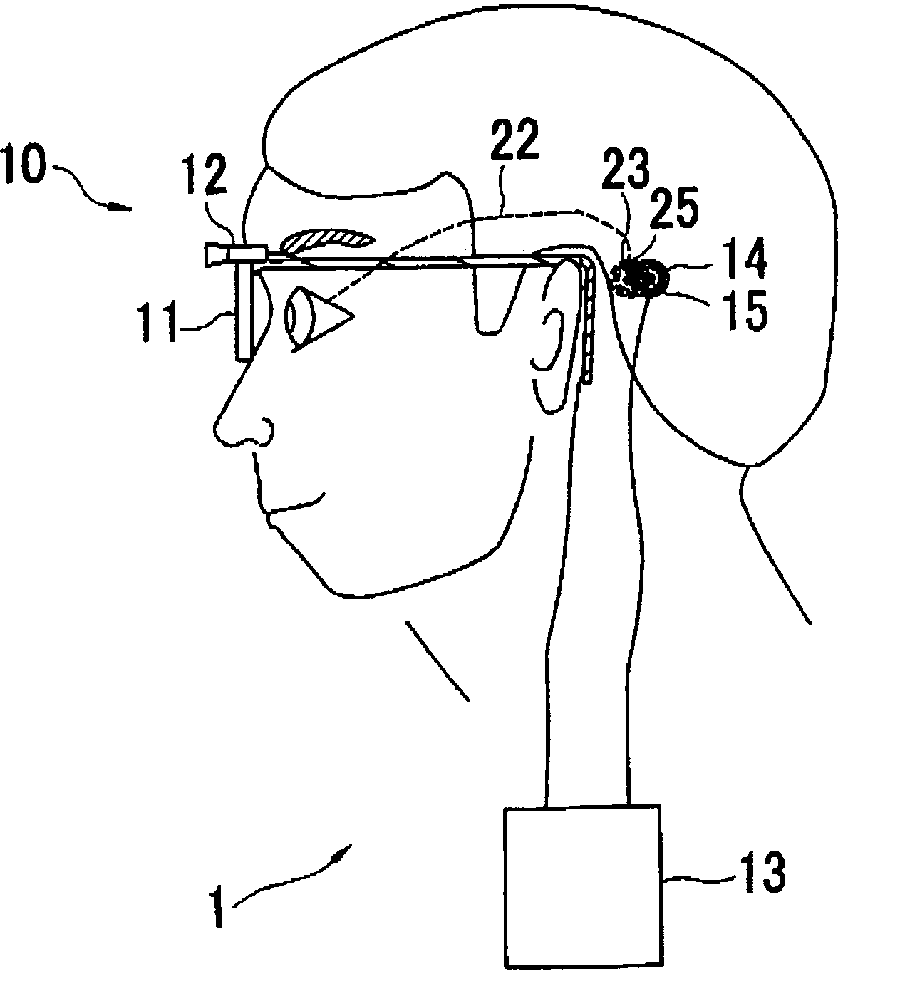
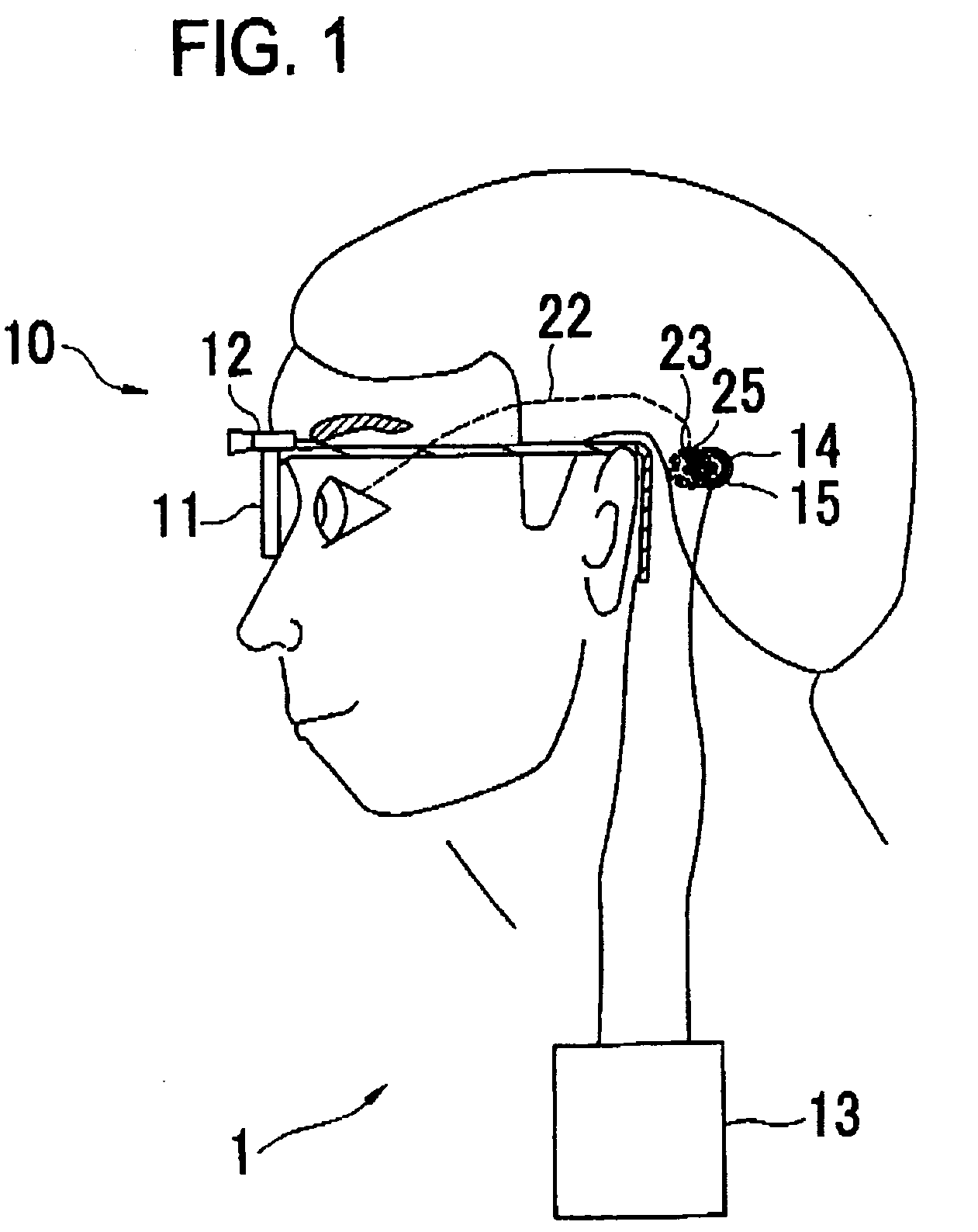
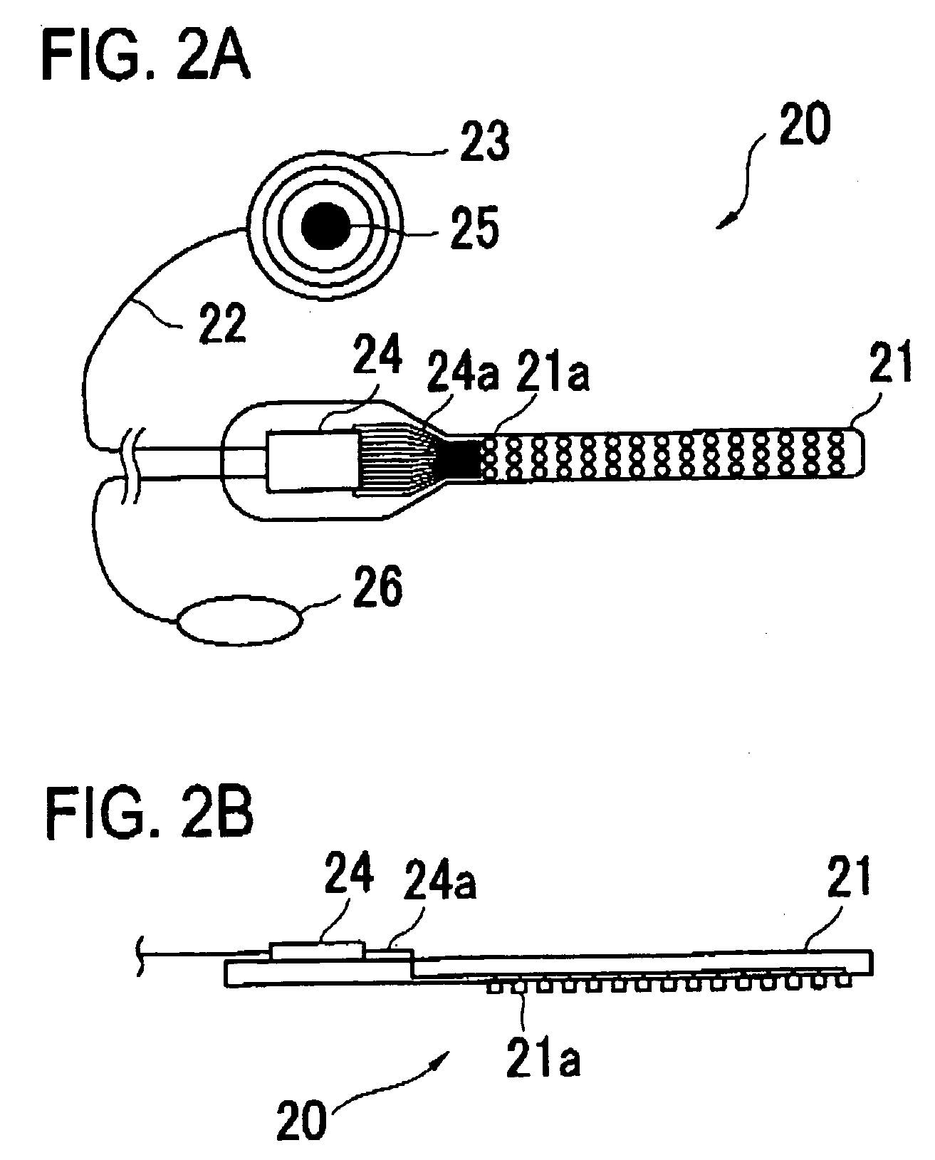
[0016] A detailed description of a preferred embodiment of the present invention will now be given referring to the accompanying drawings. FIG. 1 is a schematic structural view of a visual restoration aiding device in the present embodiment. FIG. 2 is a schematic structural view of an internal device of the visual restoration aiding device. FIG. 3 is a view showing a state where the internal device is placed in an eye. FIG. 4 is a schematic block diagram of a control system of the device.

[0017] A visual restoration aiding device 1 mainly includes an external device 10 which photographs the external world, or captures surrounding images, and an internal device 20 which applies electrical stimulation to the cells constituting a retina to induce the restoration of vision. The external device 10 includes a visor 11 which a patient will put on, a photographing unit 12 such as a CCD camera mounted on the visor 11, an external unit 13, and a transmitting unit 14 including a primary coil. ...


PUM


Abstract

A visual restoration aiding device for restoring vision of a patient, comprises: a substrate which will be placed on or under a retina, a choroid or a sclera of a patient's eye; a plurality of electrodes arranged on the substrate for applying electrical stimulation pulse signals to cells constituting the retina; a photographing unit which photographs an object to be recognized by the patient; and a control unit which controls output of the electrical stimulation pulse signals from each electrode based image data captured by the photographing unit. The number of the electrodes placed on the substrate is less than the number of electrodes that can simultaneously output the electrical stimulation pulse signals based on the image data corresponding to one frame. The control unit is configured to sequentially output the electrical stimulation pulse signals at predetermined time interval based on the divided image data corresponding to one frame so as to allow the patient to recognize the image corresponding to one frame by joining two or more divided sections of the image corresponding to one frame.

Description

BACKGROUND OF THE INVENTION [0001] 1. Field of the Invention [0002] The present invention relates to a visual restoration aiding device for inducing restoration of vision. [0003] 2. Description of Related Art [0004] There have been proposed a visual restoration aiding device for inducing restoration of vision by applying electrical stimulation to cells constituting a retina from electrodes placed (implanted) in an eye (see U.S. Pat. No. 5,109,844, U.S. Pat. No. 5,935,155). In the case where such device is used for allowing a patient to have a wide visual field and recognize an object with a good resolution, it is necessary to place many electrodes on the retina, a choroid or a sclera. However, in view of device design or operative method, and further load on a patient, there is a limit to the number of electrodes allowed to be placed. It is desired that the number of electrodes is as small as possible. SUMMARY OF THE INVENTION [0005] The present invention has been made in view of th...

Claims


Application Information

Patent Timeline
Patent Type & Authority Applications(United States)
IPC IPC(8): A61N1/32
CPCA61N1/0543A61N1/36046
Inventor TANO, YASUOFUJIKADO, TAKASHI
Owner NIDEK CO LTD
Learn More