
System for providing traffic information

Inactive Publication Date: 2006-04-06
DEKOCK BRUCE W +2
View PDF99 Cites 85 Cited by
  • Summary
  • Abstract
  • Description
  • Claims
  • Application Information

AI Technical Summary

Benefits of technology

[0020] The various aspects of the present invention have one or more of the following advantages. The present invention allows a commuter to obtain traffic information at any time, without waiting for a report to be broadcast. The present invention also allows detailed information relating to traffic conditions based on measurements of the traffic, such as the average vehicular speed or traffic density, to be supplied for a plurality of locations along a road. The invention also allows the convenient display of information in a readily understood form to the user, such as a graphical display.

Problems solved by technology

Unfortunately, the prior art methods of providing traffic information to commuters do not allow commuters to evaluate the extent to which there is congestion on a highway on which the commuter may wish to travel.
Unfortunately, these reports are usually intermittent in nature.
Further, the extent of the information provided is severely limited to broad generalizations.
Some broadcasts may include multiple observers of different portions of the freeway, yet these systems also provide incomplete information relating to overall traffic patterns.
In addition, the information provided is vague, subjective, and usually limited to broad generalities relating to traffic flow.
Again, this system provides little useful information to a commuter.
However, by the time the commuter actually gets into his vehicle and enters a potentially congested area, the traffic may have changed.
Further, the information provided is limited to those areas where the traffic is being monitored and may consist of stale information.
In addition, these types of systems require manipulation by the commuter to find the relevant traffic information.
However, a commuter who is actively driving cannot operate a computer and drive at the same time.
Thus this method may additionally suffer from added cost due to manual labor, incorrect entry of data, and slow response to quickly changing traffic conditions.
Unfortunately, the use of probe vehicles may be expensive and the relevancy of the data is limited to the availability of the probe vehicles.
Unfortunately, the system taught by Lappenbusch et al. is complicated to operate and requires significant user interaction to provide relevant data, which is suitable for such “stationary” traditional computing devices.
Unfortunately, the system taught by Smith, Jr. et al. requires the user to define a set of preselected commuter routes for each route to be traveled, which may be difficult if the user is unfamiliar with the area.
In addition, Smith, Jr. et al. teach that the user should select alternative routes that are known to the user, presumably if the commute time of the preselected commuter routes are too long, which is difficult if the user is not already familiar with the area.
In this case it is expected that traffic congestion will occur in the vicinity of that point.
While all of the above systems provide some degree of traffic information for a commuter, nevertheless the above systems do not provide an efficient method of collecting and presenting objective traffic information to a commuter.

Method used


Image

  • System for providing traffic information
  • System for providing traffic information
  • System for providing traffic information

Examples


Embodiment Construction

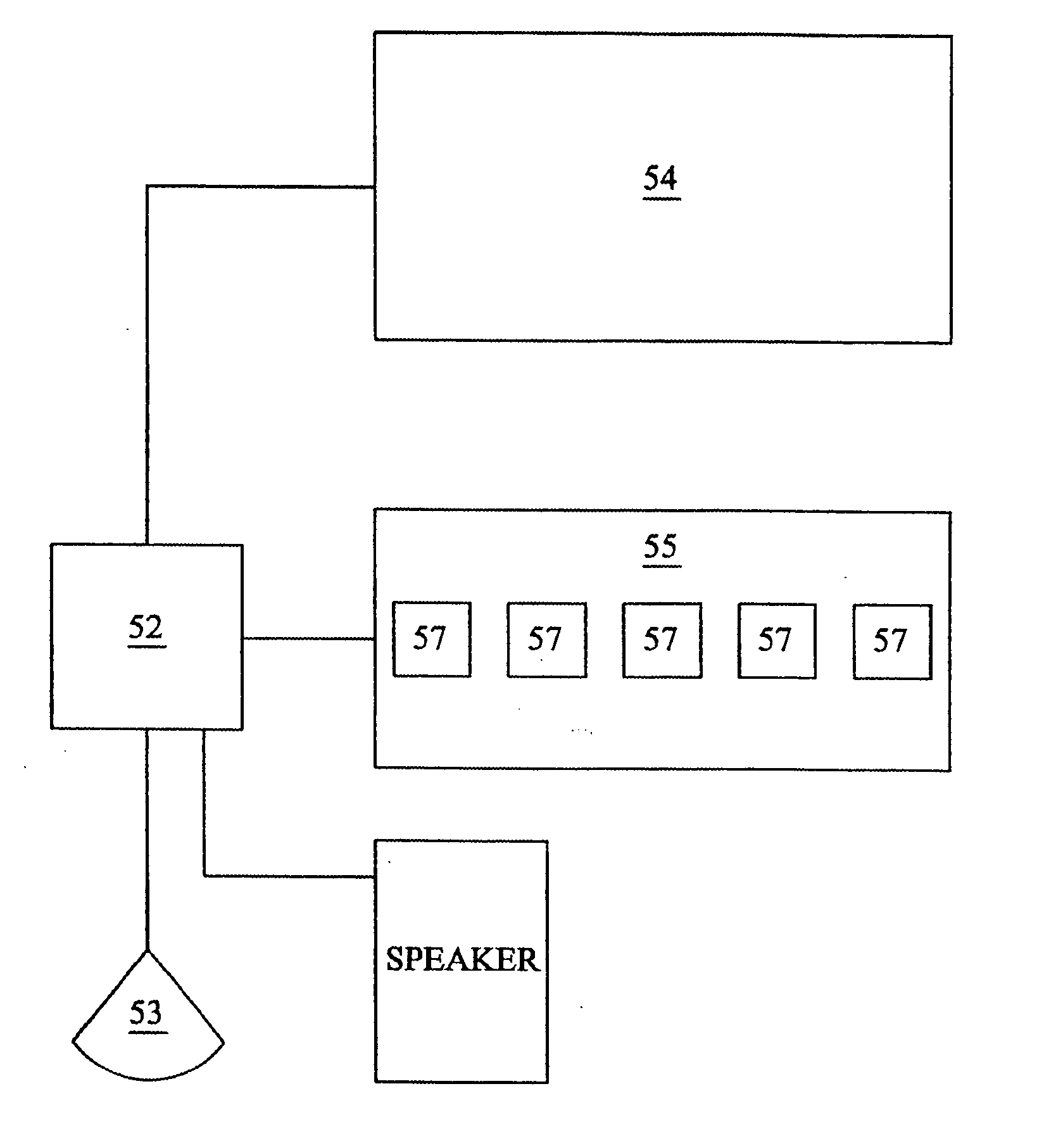
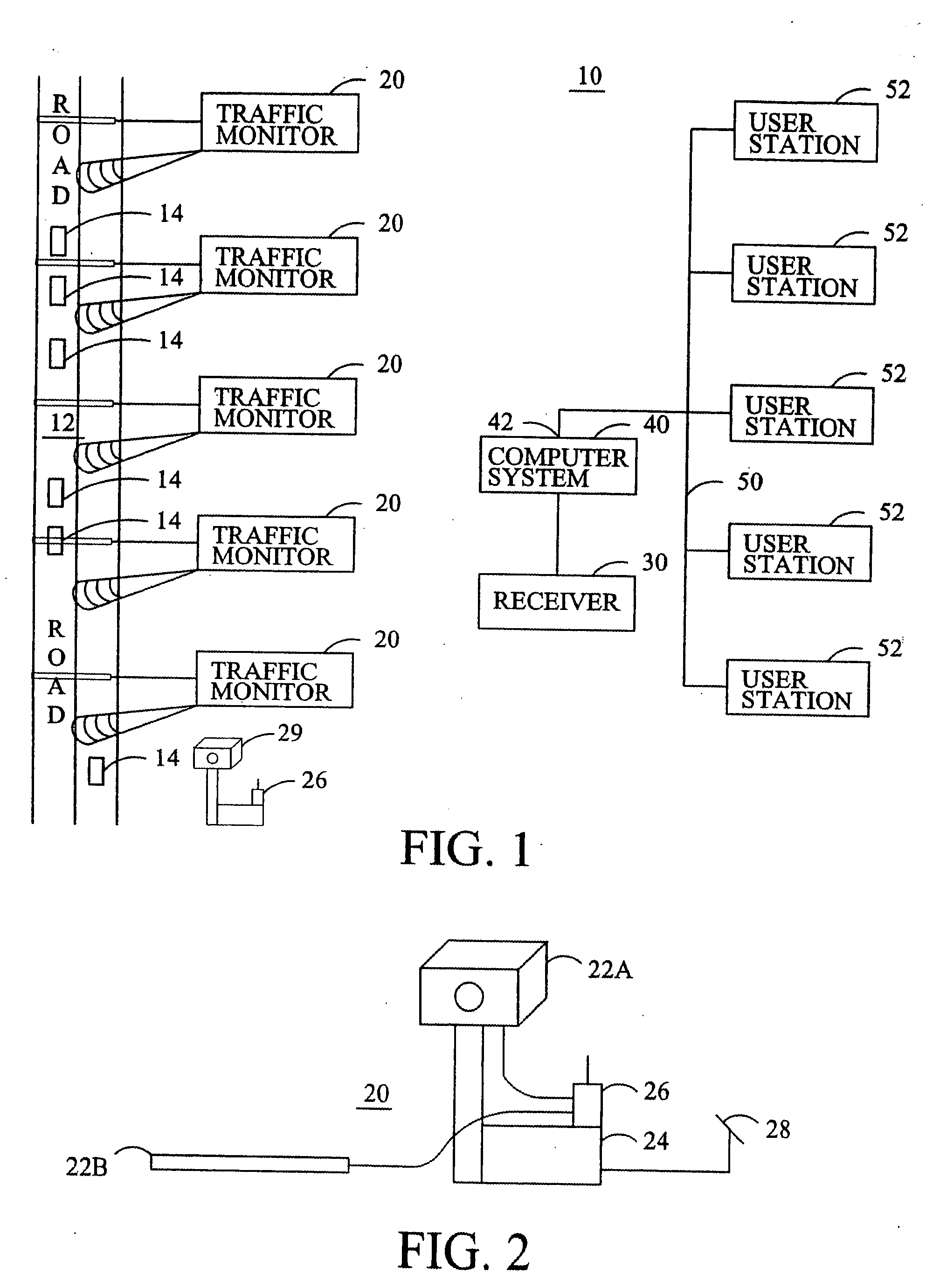
[0038] Referring now to the figures, wherein like numerals refer to like elements, FIG. 1 shows a schematic diagram of the system 10 for providing traffic information to a plurality of user stations 52 connected to a network 50. A plurality of traffic monitors 20 are arranged at spaced apart locations along a road 12. The traffic monitors 20 measure traffic information by detecting the speed (velocity) or frequency of vehicles traveling along the road (freeway or highway) 12. For example, in one embodiment, the traffic monitors 20 may detect the speed of individual vehicles 14 traveling along the road 12. Alternatively, the traffic monitors 20 may measure the frequency with which the individual vehicles 14 pass specified points along the road 12.

[0039]FIG. 2 shows a front elevational view of an exemplary embodiment of a traffic monitor 20. The traffic monitor 20 has a detector 22 for measuring or otherwise sensing traffic. FIG. 2 shows two different embodiments 22A and 22B of a det...


PUM


Abstract

A system for providing traffic information to a plurality of mobile users connected to a network. The system comprises a plurality of traffic monitors, each comprising at least a traffic detector and a transmitter, the traffic detector generating a signal in response to vehicular traffic and the transmitter transmitting the signal. A receiver receives the signals from the traffic monitors. A computer system is connected to the receiver and is further connected to the network. The computer system in response to a request signal received from one of the users transmits in response thereto information representative of the signals transmitted by the traffic monitoring units. Alternative systems for gathering traffic information are disclosed.

Description

CROSS-REFERENCE TO RELATED APPLICATIONS [0001] This application is a division of U.S. patent application Ser. No. 10 / 880,409, filed Jun. 28, 2004, which is a continuation of U.S. patent application Ser. No. 10 / 367,162, filed Feb. 13, 2003; which is a continuation of U.S. patent application Ser. No. 10 / 218,850, filed Aug. 13, 2002, now U.S. Pat. No. 6,574,548, issued Jun. 3, 2003, which is a continuation of U.S. patent application Ser. No. 09 / 550,476, filed Apr. 14, 2000, now U.S. Pat. No. 6,466,862, issued Oct. 15, 2002, which is a continuation of U.S. patent application Ser. No. 09 / 352,156, filed Jul. 12, 1999; which claims the benefit of U.S. Provisional App. No. 60 / 130,399, filed Apr. 19, 1999; U.S. Provisional App. No. 60 / 166,868, filed Nov. 22, 1999; and U.S. Provisional App. No. 60 / 189,913, filed Mar. 16, 2000.BACKGROUND OF THE INVENTION [0002] The present invention relates to a system for providing traffic information, and more particularly a system for providing traffic info...

Claims


Application Information

Patent Timeline
IPC IPC(8): G08G1/00
CPCG08G1/01G08G1/04
Inventor DEKOCK, BRUCE W.RUSSELL, KEVIN L.QIAN, RICHARD J.
Owner DEKOCK BRUCE W
Learn More