Speaker having spacer ring inside frame

a technology of spacer ring and speaker, which is applied in the field of speakers, can solve the problems of increasing the number of constituent parts, complicated production of diaphragm, and increasing production cost, and achieves the effects of enhancing durability and therefore reliability, good reproducing bass sound, and absorbing rapid vibration from the diaphragm

Inactive Publication Date: 2006-04-13
MINEBEA CO LTD
View PDF4 Cites 32 Cited by
  • Summary
  • Abstract
  • Description
  • Claims
  • Application Information

AI Technical Summary

Benefits of technology

[0012] The present invention has been made in the light of the above problems, and it is an object of the invention to provide a speaker, in which the outer diameter of the spider can be set to be equal to or larger than the outer diameter of the surround, and in which the surround outer is securely protected so as not to peel off when a large input is applied to the speaker, thereby enhancing the durability and accordingly the reliability as well. And another object thereof is to provide a speaker, in which no special means or components are required for keeping the frame free from resonance, which reduces the number of constituent components realizing cost reduction.
[0021] In the present invention, since the outer edge of the surround fixedly attached to the diaphragm is bonded to the surround edge receiving portion provided on the spacer ring which is disposed inside the frame, the diaphragm and the voice coil bobbin with the voice coil wound thereon can be securely held in a prescribed position by means of the surround and the spider both functioning as suspensions, with the spider having an outer diameter equal to or larger than the outer diameter of the surround. Accordingly, the speaker of the present invention has its lowest resonant frequency (of) kept as low as possible and is good for reproducing a bass sound.
[0022] Also, since the spacer is adapted to receive the entire outer edge of the surround regardless of the configuration of the diaphragm, the spider can always be dimensioned to have an outer diameter equal to or larger than the outer diameter of the surround regardless of the type of speaker. This also enables the entire outer edge of the surround to be sandwiched between the spacer ring and the gasket, so that the surround edge does not peel off even when the diaphragm vibrates heavily with a large input, thereby enhancing durability and therefore reliability.
[0023] Further, since the spacer ring is formed of ABS resin or elastomer, vibration from the diaphragm is absorbed quickly. Accordingly, the frame and the magnetic circuit do not have to have a vibration absorbing material bonded thereon, resulting in reduced production cost.

Problems solved by technology

In the first speaker, since the outer diameter of the diaphragm is larger than the inner diameter of the surround, the diaphragm has to be uniquely configured such that the lower face of the outer periphery of the diaphragm is fixedly attached to the inner edge of the surround, and also since the entire weight balance of the diaphragm must be properly maintained, the production of the diaphragm is complicated.
These factors will push up production cost.
As the steel plate has a small internal loss, the frame and the magnetic circuit must have butyl rubber or the like bonded on their surfaces so as to absorb the resonance generated by the diaphragm vibrating, which increases the number of constituent components thereby leading to increased cost.
Also, in the second speaker, the cutaways, which can be made on a frame shaped rectangular or elliptic, cannot be made when the frame is shaped circular.
Further, in this speaker, since the outer edge of the surround has no support or protection provided on its lower face while having the gasket fixedly provided on its upper face, when the diaphragm moves downward considerably with a large input applied to the speaker, the surround including its outer edge is moved together downward considerably thereby possibly separating the surround edge from the gasket, which raises a problem with reliability.

Method used


Image

  • Speaker having spacer ring inside frame
  • Speaker having spacer ring inside frame
  • Speaker having spacer ring inside frame

Examples


Embodiment Construction

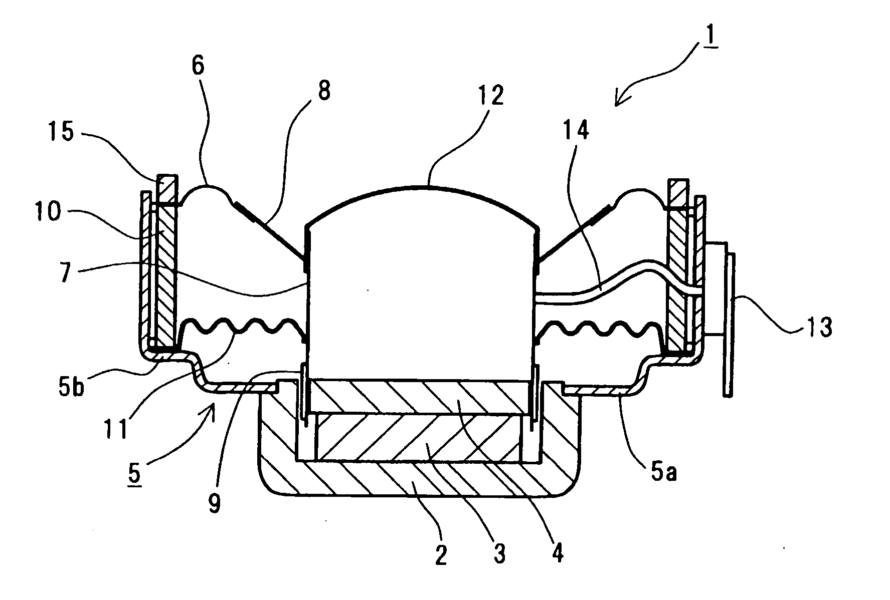
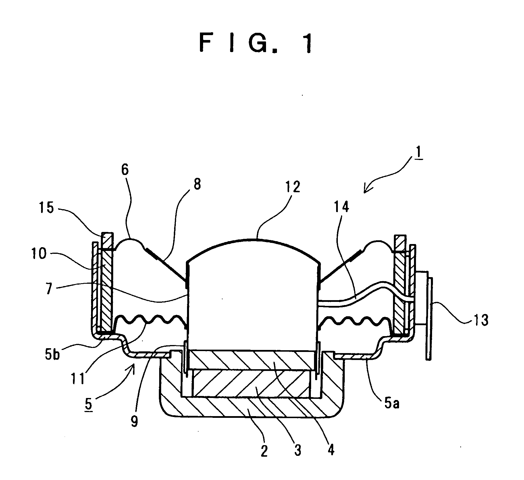
[0034] Preferred embodiments of the present invention will be described in detail with reference to the drawings.

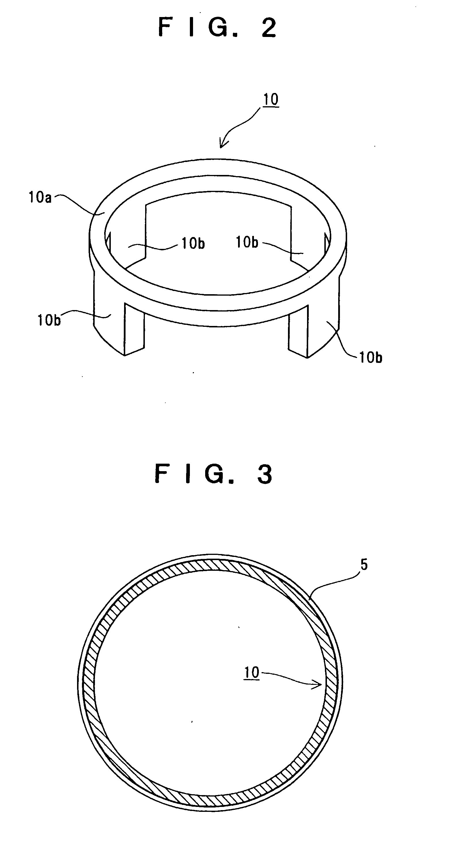
[0035] Referring to FIG. 1, a speaker 1 of the present invention generally comprises: a magnetic circuit comprising a pot yoke 2 shaped hollow-cylindrical and having a closed bottom and an open top, a magnet 3 formed of a permanent magnet, shaped cylindrical, and disposed at the center of the bottom of the pot yoke 2, and pole piece 4; a frame 5 joined to the magnetic circuit; a surround 6 shaped like a doughnut and consisting of a half-rolled portion, an outer edge (numbered 6a in FIGS. 6 and 7 and to be referred to as “surround edge” as appropriate), and an inner edge; a voice coil bobbin 7; a voice coil 9 wound on the voice coil bobbin 7; a diaphragm 8 defining an outer periphery and an inner periphery, and having the surround 6 on the outer periphery and the voice coil bobbin 7 on the inner periphery; a spacer ring 10 fixedly disposed inside the frame 5 as shown in F...


PUM


Abstract

A speaker comprises: a magnetic circuit composed of a pot yoke, a magnet, and a pole piece; a diaphragm shaped conical, defining an outer periphery and an inner periphery, and having a surround half-rolled and fixedly disposed at the outer periphery and a voice coil bobbin with a voice coil wound thereon, fixedly disposed at the inner periphery; a spider having an outer diameter equal to or larger than the outer diameter of the surround; a frame having the magnetic circuit fixedly disposed at its central opening; and a spacer ring fixedly disposed inside the frame, and having a surround edge receiving portion adapted to fixedly receive the entire outer edge of the surround thereon.

Description

[0001] This application is a continuation of U.S. patent application Ser. No. 10 / 366,402 filed Feb. 14, 2003; which claims priority to Japanese Patent Application No. 2002-38927 filed Feb. 15, 2002, the contents of which are incorporated herein by reference in its entirety.BACKGROUND OF THE INVENTION [0002] 1. Field of the Invention [0003] The present invention relates to a speaker for use in TVs, radios, personal computers, and audio equipments, and more particularly to a speaker which is with a lowest resonant frequency, is good for reproducing a bass sound, and is excellent in durability and reliability. [0004] 2. Description of the Related Art [0005] A dynamic speaker using a conical diaphragm is structured such that a diaphragm is disposed inside a frame so as to be suspended by way of a surround half-rolled and a spider, both of which work as suspensions, so that a voice coil bobbin having a voice coil wound thereon and fixedly attached to the inner perimeter of the diaphragm ...

Claims


Application Information

Patent Timeline
Patent Type & Authority Applications(United States)
IPC IPC(8): H04R9/06H04R9/00H04R7/12H04R7/16H04R7/18H04R9/02
CPCH04R7/18H04R9/06
Inventor SATO, EIJI
Owner MINEBEA CO LTD
Why Eureka
Try Eureka