
Image combination device, image combination method, image combination program, and recording medium containing the image combination program

Inactive Publication Date: 2006-04-13
SHARP KK
View PDF20 Cites 104 Cited by
  • Summary
  • Abstract
  • Description
  • Claims
  • Application Information

AI Technical Summary

Benefits of technology

[0034] The “amount of distortion correction” is an amount of correction performed so as to correct an amount of change that remains uncorrected after a change of the image to be photographed caused by a change in the position and / or direction of the camera and / or the lens is corrected incompletely by parallel movement, rotation, and / or expansion or reduction. For example, the “amount of distortion correction” includes an amount of perspective correction or the like. “Perspective” is an effect that, for example, an upper portion of a high building taken in a photograph looks smaller than a lower portion due to the law of perspective, even through the actual size is the same.
[0091] If there is overlap, the image may be photographed again after resolving the overlap by moving the object or the camera. Helping the photography in this case means, for example, making it easier for the user to know whether or not there is overlap, and giving the user information (here, the composite image) on how much the object or the camera should move to avoid the overlap.

Problems solved by technology

However, it is a painful job to carry around a tripod.
On the other hand, one may feel ill at ease to ask a stranger to take a photograph.
However, roughly speaking, these prior arts have the following two problems.
The first problem is as follows: if the object region of the reference image is merely carved out and superimposed on another image, (1) an object in the composite image could have a missing part, and / or (2) an unnecessary region could be combined, if the object region is specified imprecisely.
In addition, (3) even if the object region is specified precisely, the boundary between combined images could look slightly unnatural.
This makes the composite image look obviously unnatural.
In this case, the composite image looks very unnatural, because the background suddenly changes at the specified object region.
Accordingly, the resultant composite image looks unnatural.
However, there is a possibility that errors of one, two, or several pixels might occur.
It is not easy to specify the outline by hand with a pixel-size precision.
This is because specifying by pixel is not precise enough to define the outline of the specified object region.
Therefore, the problems (1) to (3) cannot be solved by merely performing positioning of the images to be superimposed.
As a result, the composite image looks unnatural.
The second problem is as follows: if photographs are taken for the purpose of combining an object region of a reference image with an image to be photographed that includes another object, and sufficient attention is not paid to the positions of the objects at the time of shooting, object regions of the respective images might be superimposed on each other in the composite image, or the object of one of the images might extend off the composite image.
However, the foregoing method is inconvenient in that high-level processing such as the processing for recognizing the object regions, the processing for judging whether or not the object regions are superimposed on each other, and the processing for judging whether or not an object region extends off the composite image, must be performed by human.
It is also inconvenient that the object region of the reference image must be specified manually.

Method used


Image

  • Image combination device, image combination method, image combination program, and recording medium containing the image combination program
  • Image combination device, image combination method, image combination program, and recording medium containing the image combination program
  • Image combination device, image combination method, image combination program, and recording medium containing the image combination program

Examples


embodiments 1

[0147] With reference to the drawings, the following describes embodiments of the present invention.

[0148] First, definitions of terms are set forth below.

[0149]“First object” and “second object” are objects to be combined. In general, these objects are persons, but they can be articles or the like. Strictly speaking, the “first object” is a region where pixel values do not correspond when a background portion of a background image and a background portion of a first object image overlap at least partially. In other words, any region where there is a change has a possibility to be a “first object region”. However, “any region where there is a change” could include a minor change in the background portion caused by leaves waving in the breeze. It is therefore preferable to ignore minor changes and small regions. The same holds true with the “second object”.

[0150] If the object is a person, the object is not necessarily a single person; a plurality of persons may collectively const...

embodiment 2

[0596] With reference to the drawings, the following describes another embodiment of the present invention. In EMBODIMENT 1, the background image is used in addition to the first object image and the second object image, and the background image does not include an object, but includes a background portion that corresponds to each object image at least partially. In EMBODIMENT 2, on the other hand, the background image is not used in combining images.

[0597] Again, definitions of terms are set forth below.

[0598]“First object” and “second object” are objects to be combined. In general, these objects are often persons, but they can be articles or the like. Strictly speaking, the “first object” is a region where pixel values do not correspond when a background image and a first object image are superimposed on each other so that at least a part of a background portion overlaps. In other words, any region where there is a change has a possibility to be a “first object region”. However,...


PUM


Abstract

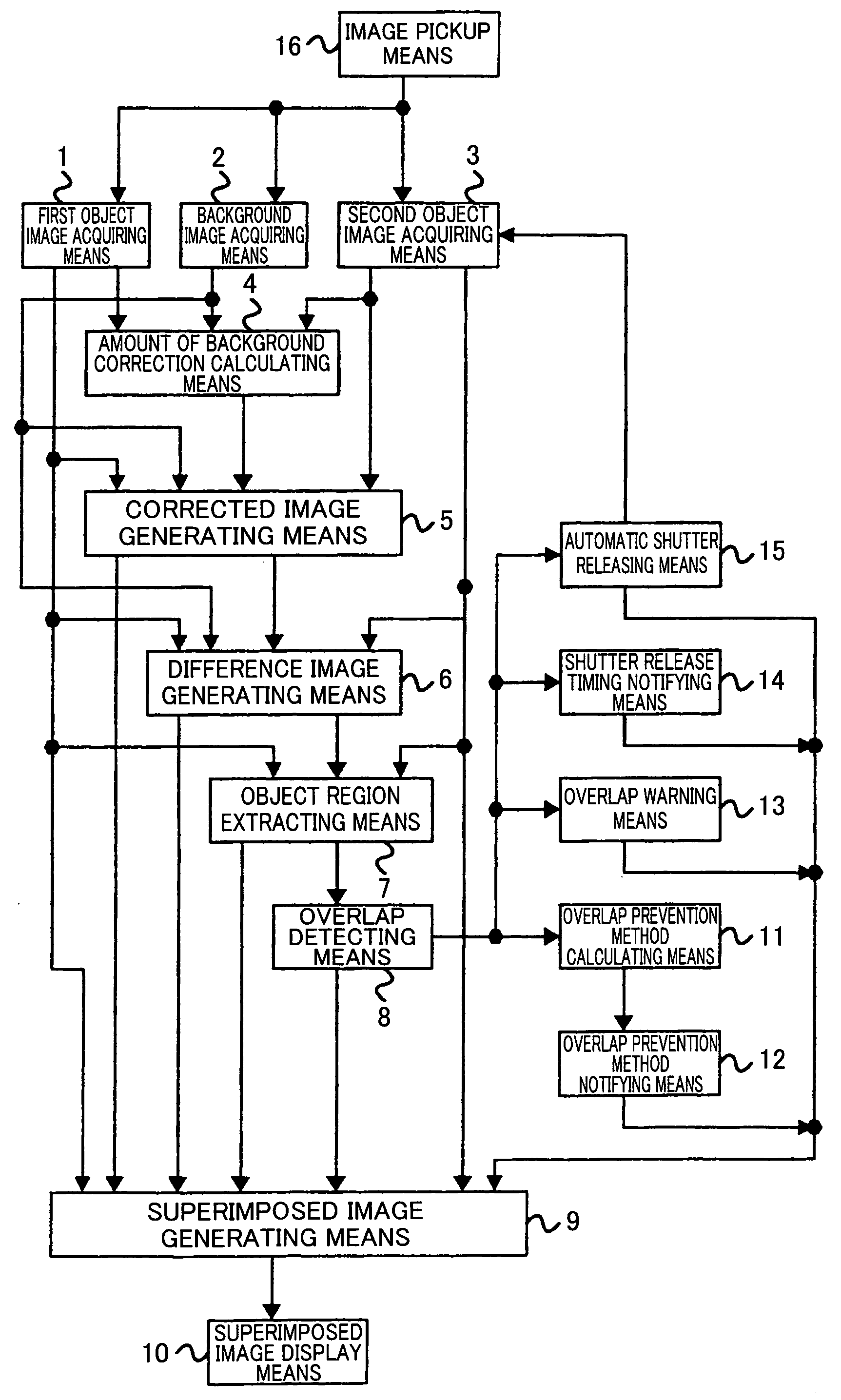
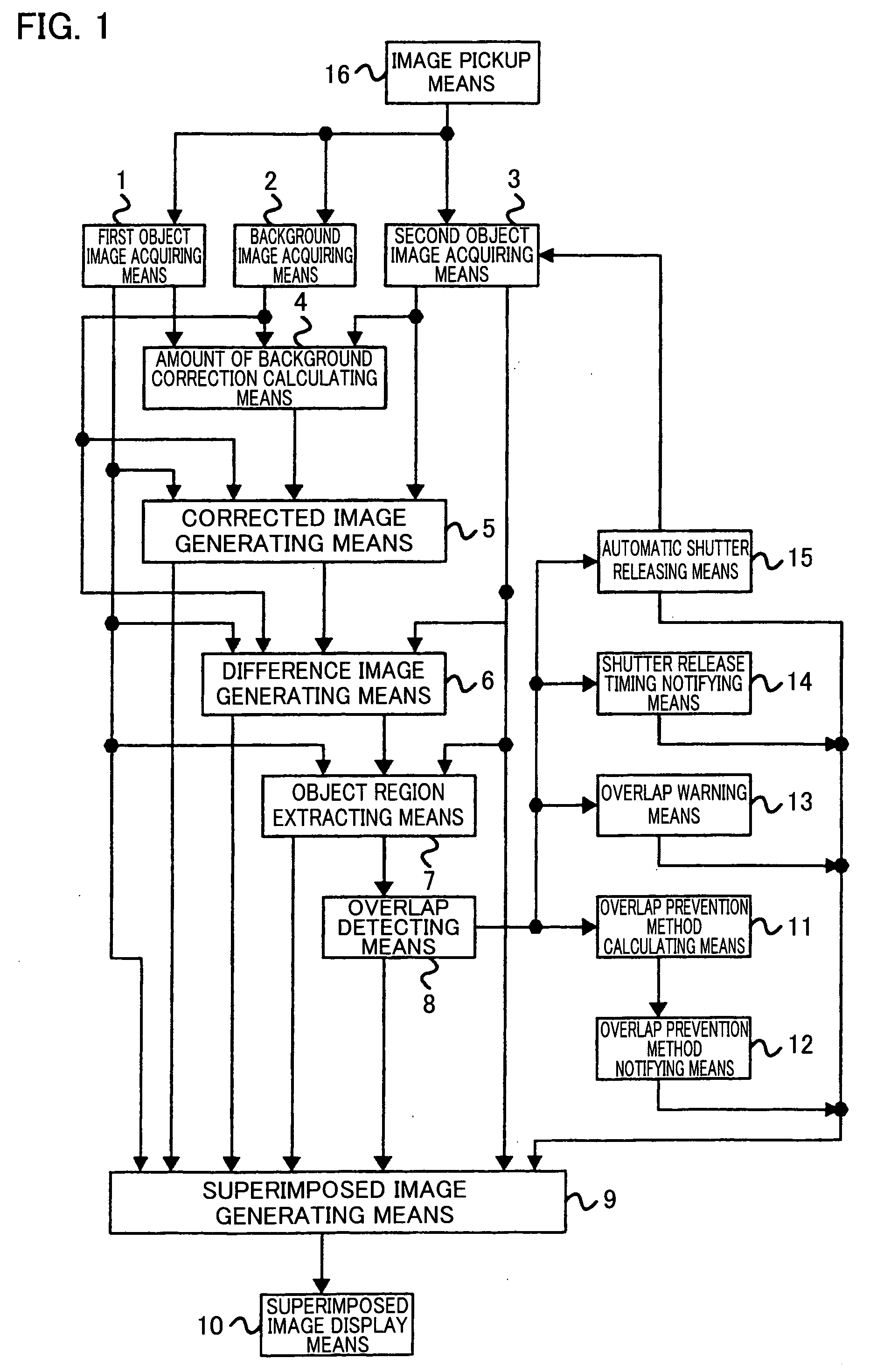
An image combination device acquires a first object image, a second object image, and a background image by first object image acquiring means (1), second object image acquiring means (3), and background image acquiring means (2) and by using one of the three images as a standard image, generates two corrected images by background correction amount calculating means (4) and corrected image generating means (5), so that background portions of the two images correspond. Superimposed image generating means (9) generates an image by superimposing the standard image and one or two of the corrected images. According to this arrangement, since the backgrounds of the superimposed images correspond to each other, the first object and the second object, which have been photographed separately, can be combined without causing an impression that these objects are combined to the background artificially.

Description

TECHNICAL FIELD [0001] The present invention relates to devices, methods, programs, and program mediums for combining a plurality of objects, which are imaged separately, into a single image so that the objects look as if they existed spontaneously. The devices, methods, programs, and program mediums help to photograph / combine objects without causing overlap of the objects. BACKGROUND ART [0002] If two persons wish to have their photographs taken by using a film camera or digital camera while they are standing next to each other, for example, they must use a tripod and a self-timer, or ask a third person such as a stranger to take their photograph. [0003] However, it is a painful job to carry around a tripod. On the other hand, one may feel ill at ease to ask a stranger to take a photograph. [0004] In view of this problem, Japanese Publication for Laid-Open Patent Application, Tokukai 2000-316125 (publication date: Nov. 14, 2000) discloses an image combination device that can extrac...

Claims


Application Information

Patent Timeline
IPC IPC(8): G06K9/36H04N5/235H04N5/272
CPCH04N5/2353H04N5/272H04N23/73
Inventor HIROSAWA, MASASHI
Owner SHARP KK
Learn More