
Device for storing projectile balls and feeding them into the projectile chamber of a gun

Active Publication Date: 2006-04-20
KORE OUTDOOR US INC
View PDF88 Cites 28 Cited by
  • Summary
  • Abstract
  • Description
  • Claims
  • Application Information

AI Technical Summary

Benefits of technology

[0004] The solution according to the invention lies in features which provide for a device for storing balls and for feeding said balls into the ball chamber of a hand gun. A ball container is used for storing the balls, having a feeder tube attached to it which leads to the arm. A feeder is provided for feeding the balls into the feeder tube, the feeder being driven by a motor. When the motor is switched off, a spring device helps maintain the feeding pressure on the balls inside the tube whose spring travel is at least the magnitude of the diameter of the ball. This ensures that immediately following a discharge and opening of the projectile chamber, the spring tension pushes the next ball into the projectile chamber, this process not requiring any previous switching on of the feeder motor. The traction force of the motor which ensures the rotation of the feeder is transmitted to the feeder via a slip clutch, that limits torque transmission.
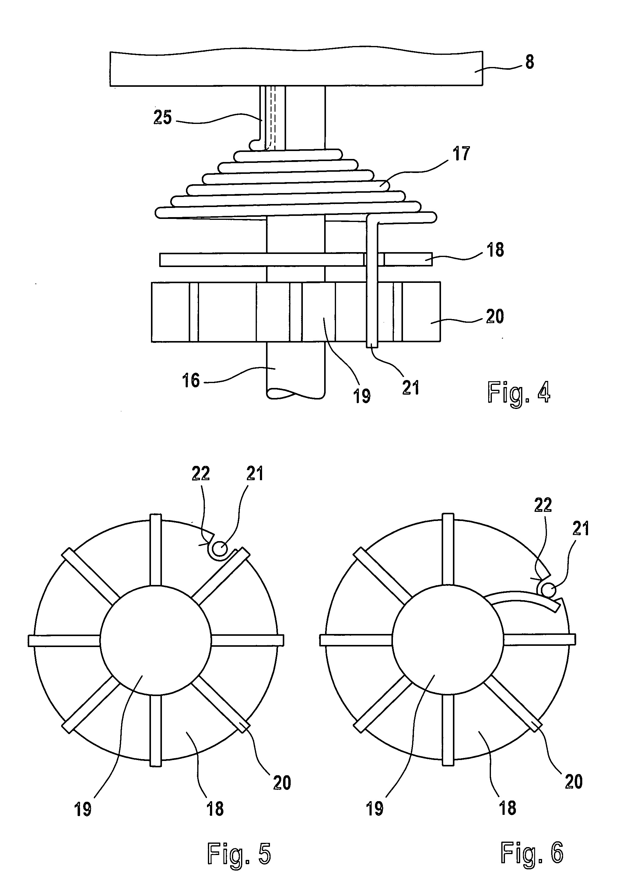
[0006] The protrusions of the spring element and / or the protrusions of the transmission element are of a flexible kind. If the power transmission from the protrusions of the transmission element to the protrusion of the spring element becomes too great, the flexible protrusion bends in the direction of the force. The protrusions slip past each other and the protrusion of the spring element comes to bear on the next protrusion of the transmission element. This way, the torque that can be transmitted from the motor to the feeder is limited. The torque threshold at which the protrusions slip past each another, is set in such a way that the balls are not damaged.
[0009] In general, loading the spring by the drive motor has the effect that the position of the protrusion of the feeder element changes in relation to the protrusion of the transmission element. The effect of this could be that the maximum possible power transmission from the spring element to the transmission element changes. In order to maintain the same position of the protrusions relative to one another, a distance holder can be provided. The distance holder swings freely around the same axle as the transmission element, thereby keeping the protrusion of the spring element at a constant distance from the axle.
[0010] It is essential that the ball, which is driven by the feeder into the feeder tube, moves along a defined path. If the ball is not on the defined path there is the risk that the ball is pushed against the edge of the entrance to the feeder tube instead of entering the feeder tube. The force of the feeder can damage the ball. To minimize the risk of damage the device can comprise a flexible element above the feeder adjacent to the feeder tube. The flexible element is fixed to the ball container with its one end. A ball that is not in the correct position relative to the feeder touches the flexible element, before it is pushed against the edge of the feeder tube. The flexible element deflects the ball back into the ball container.
[0012] The feeder can transport balls effectively only when it is ensured that the balls arrive in the feeder areas of the feeder. If the feeder is a rotary feeder in which the feeding chambers are located at the perimeter, a cone-shaped protrusion can be provided on the upper side of the feeder. Balls lying on this protrusion roll down its sides and come to rest in the feeder chambers.

Problems solved by technology

The traction force of the motor which ensures the rotation of the feeder is transmitted to the feeder via a slip clutch, that limits torque transmission.
This way, the torque that can be transmitted from the motor to the feeder is limited.

Method used


Image

  • Device for storing projectile balls and feeding them into the projectile chamber of a gun
  • Device for storing projectile balls and feeding them into the projectile chamber of a gun
  • Device for storing projectile balls and feeding them into the projectile chamber of a gun

Examples


Embodiment Construction

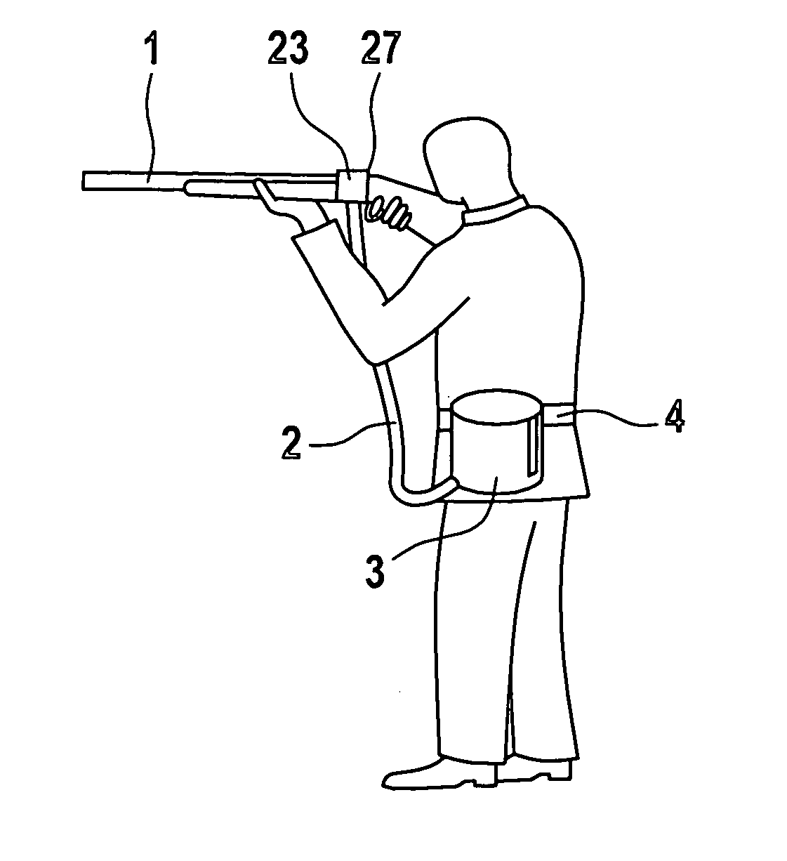
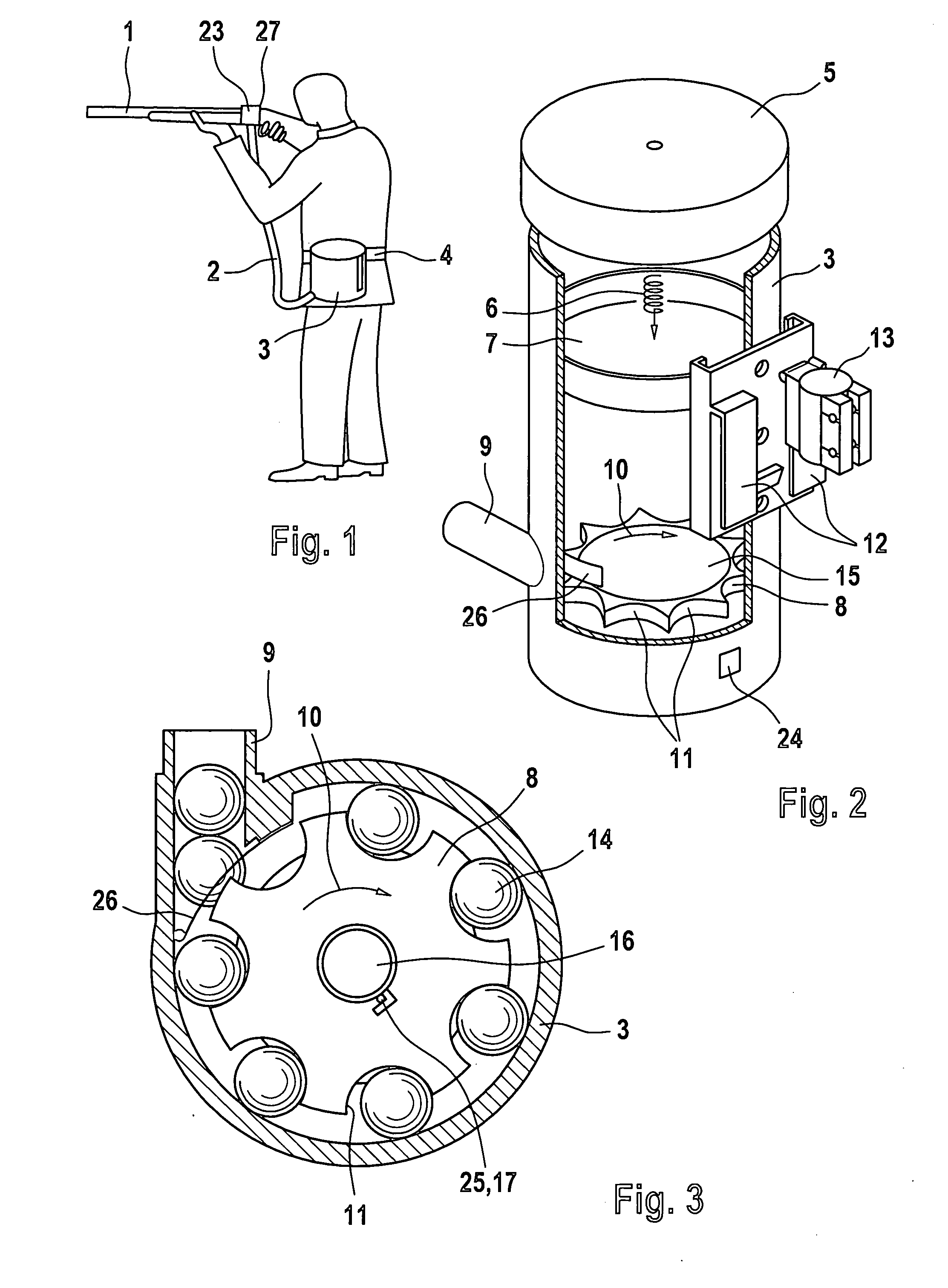
[0020] According to FIG. 1, a shooter uses an arm 1, for example an air gun for so-called paint balls, which is connected with a ball container 3 containing balls 14, through a flexible feeder tube 2. The balls 14 are fed in a continuous process through a feeder 8 (to be described below) to the projectile chamber of the gun 1. In this process, they are under pressure from a spring, so that every time a ball is fired and the empty projectile chamber opens, a new ball is fed from the feeder tube 2 into the projectile chamber. The ball container 3 is attached to the belt 4 of the shooter.

[0021] According to FIG. 3, the ball container 3 is of a cylindrical shape and provided with a cover lid 5 connected with a pressure plate 7 via a schematically indicated tension spring 6. The pressure plate 7, under the impact from the spring 6, pushes the contents of the container away from the open end of the container, shut by the lid, to its other end. At this other end is the feeder 8 that feeds...


PUM


Abstract

The invention relates to a device for feeding ball-like ammunition, so-called paint balls, into the projectile chamber of a sporting arm. The magazine is arranged separately from the arm and is connected to same by means of a feeder tube. A motor-driven feeder feeds the balls from the ball container into the feeder tube. In so doing, a spring element stores the traction from the motor, so that, even when the motor stops, balls can still be transported using the energy stored in the spring element. The traction from the motor is transmitted via a connection or clutch consisting of a spring element and a transmission element. Protrusions are arranged on both the spring element and the transmission element, which come to bear on each other for transmitting traction. The protrusions are at least partially flexible, so that the transmitted force is limited. This way, explosion of the balls from excessive pressure is prevented. In addition, the feeder is connected with the drive element for the feeder, which is under pressure from the spring, by means of a bayonet-like connection. This way, the feeder can be removed from the ball container with one manipulation to facilitate the cleaning of the ball container in the event a ball explodes in spite of this.

Description

BACKGROUND OF THE INVENTION [0001] In the case of sporting arms with ball-like ammunition, so-called paint balls, the general problem is feeding the balls into the projectile chamber of the arm. In the simplest version, a magazine is mounted above the projectile chamber, from which the individual balls enter the projectile chamber through the force of gravity. [0002] Also known is patent U.S. Pat. No. 6,327,953, whose disclosure is herewith included in the disclosure of the present application and whose characteristics are part of the disclosure of the present application. There, the magazine is arranged at a distance from the arm; it is carried in any other place. The transport of the ammunition from the magazine to the arm is by way of a long, flexible feeder tube not impairing the maneuverability of the arm. A motor-driven feeder exercises mechanical pressure on the balls so that the tube is constantly filled with balls and that new balls enter the feeder tube when the first ball...

Claims


Application Information

Patent Timeline
IPC IPC(8): F41B11/02
CPCF41B11/53F41A9/02
Inventor ANDRESEN, HEDDIES
Owner KORE OUTDOOR US INC
Learn More