Catalyst

Active Publication Date: 2017-04-20
SHELL USA INC
View PDF3 Cites 3 Cited by
  • Summary
  • Abstract
  • Description
  • Claims
  • Application Information

AI Technical Summary

Benefits of technology

[0022]A further advantage of the present invention relates to exothermic reactions. In these reactions heat is generated which has to be exported out-of the catalyst structure. The direction of the channels in the catalyst allow for an efficient transport of heat by the fluid from the inside of the catalyst.
[0023]In case a single catalyst fills a reactor tube or a catalyst being a catalyst structure snugly fitting in a reactor tube, the channels in the catalyst are orientated such that reaction fluid and hydrocarbon product can flow to the reactor tube wall. In the reactor the reactor tubes are located within a jacket containing water. The heat of reaction raises the temperature of the catalyst bed within each tube. This thermal energy is transferred to the tube wall heating the water in the jacket. The heated water in turn is cooled/condensed in another heat exchanger outside of the reactor. By allowing the reaction medium and product to flow to and from the reactor wall during operation heat is transferred via the reactor wall to the water heating the water and cooling the reaction medium and product. Reaction medium and product at the reactor wall can also flow from the reactor tube wall towards the center of the catalyst. This allows for the reaction medium and product to cool the catalyst.
[0024]The improved transport of heat is very beneficial in Fischer-Tropsch reactions. The Fischer-Tropsch reaction is very exothermic and temperature sensitive. In consequence, careful temperature control is required to maintain optimum operation conditions and desired hydrocarbon product selectivity. The fact that the reaction is very exothermic also has the consequence that when temperature control is not adequate, the reactor temperature can increase very

Problems solved by technology

The fact that the reaction is very exothermic also has the consequence that when temperature control is not adequate, the reactor temperature can increase very quickly, which carries the risk of a reactor runaway.
A reactor runaway may result in highly increased temperatures at one or more locations in the reactor.
A high-speed stop may, for example, be required when the temperature in the Fischer-Tropsch reactor increases to an unacceptable value either locally or over the entire reactor, when there is an interruption in the gas flow, or in the case o

Method used


Image

  • Catalyst
  • Catalyst
  • Catalyst

Examples


example 1

Catalyst Preparation

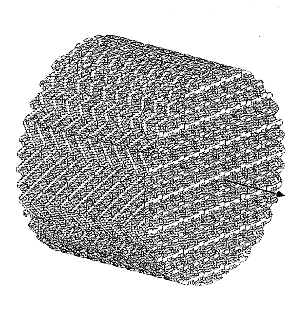
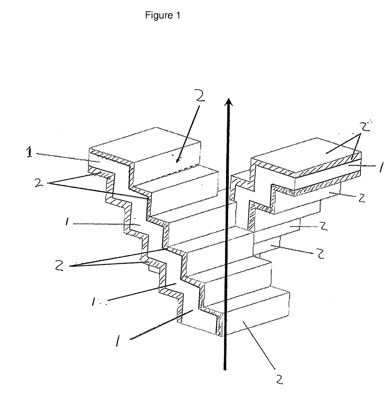
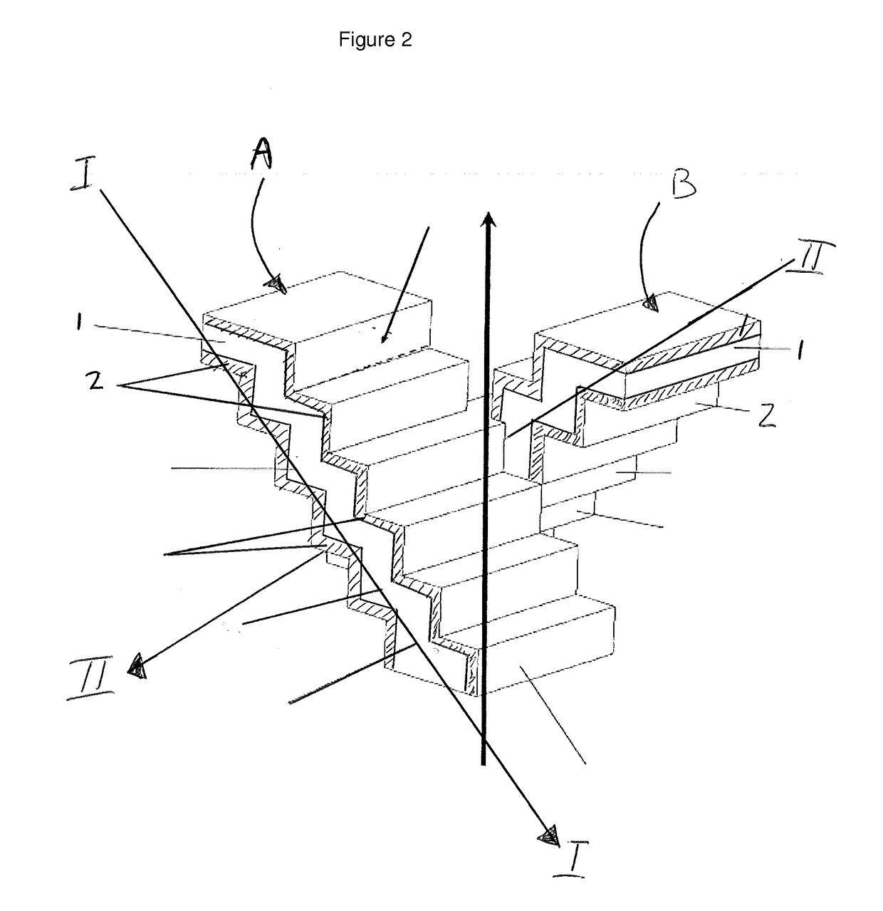
[0053]Stepped-shape substrates were obtained by means of 3D printing. The 3D printer used is CONCEPTLaser M2 3D-printer. The printer can be programmed to print a substrate as depicted in one of the figures.

[0054]In general a computer can be programmed to operate a printer such that it will manufacture a substrate by performing the steps of:[0055]i) forming a layer of a matrix material from a powder or paste;[0056]ii) binding or fusing the powder or paste in said layer according to a predetermined pattern; and[0057]iii) repeating (i) and (ii) layer upon layer to form a catalyst wherein each subsequent layer is bound or fused to a preceding layer. By repeating these steps several times a structure (the substrate) can be obtained having stepped-shape channels which correspond to the channels of a catalyst according to the present invention.

[0058]For this example two substrates were manufactured according to this method. One substrate structure was manufactured from ...

example 2

Hydrocarbon Synthesis

[0067]The catalysts obtained in example 1 were reduced and subjected to a Fischer-Tropsch synthesis. The conditions at which the Fischer-Tropsch reaction was conducted are mentioned in table 1. The comparative examples are based on extrudates and are well known in the art. These can be obtained as explained in WO97 / 00231 and can be extruded in accordance with WO2012 / 084788.

TABLE 1Comp.Sample 1Comp.Sample 2CatalystExtrudateSteppedExtrudateSteppedshape / support(alumina)(titania)Temperature488488488488(K)H2 / CO ratio1.91.91.91.9Syngas19191818pressureCO78787070conversionWTY160687156324C5+60855989selectivity(wt %)CO22.20.82.35.1selectivity(%)

[0068]From the results of Example 2 it is clear that the C5+ selectivity is much higher for the two catalysts according to the present invention.

example 3

Catalyst Preparation

[0069]A catalyst according to the present invention can be obtained by using a screen printer XH STS from ASYS EKRA. The printer can be programmed to print a catalyst as depicted in one of the figures.

[0070]In general the printer will manufacture a catalyst wherein, the catalyst has channels for a reaction fluid to flow through and said channels having walls, said walls comprising a catalytic material, by executing a method comprising the steps of:[0071]i) forming a layer of a catalytic material and a matrix material;[0072]ii) binding or fusing the powder or paste in said layer according to a predetermined pattern; and[0073]iii) repeating (i) and (ii) layer upon layer to form a catalyst wherein each subsequent layer is bound or fused to a preceding layer.


PUM

PropertyMeasurementUnit
Fractionaaaaaaaaaa
Thicknessaaaaaaaaaa
Flow rateaaaaaaaaaa

Abstract

The Fischer-Tropsch process can be used for the conversion of hydrocarbonaceous feed stocks into normally liquid and/or solid hydrocarbons. The feed stock (e.g. natural gas, associated gas and/or coal-bed methane, coal) is converted in a first step into a mixture of hydrogen and carbon monoxide (this mixture is often referred to as synthesis gas or syngas). The synthesis gas (or syngas) is then converted in one or more steps over a suitable catalyst at elevated temperature and pressure into paraffinic compounds ranging from methane to high molecular weight molecules comprising up to 200 carbon atoms, or, under particular circumstances, even more. The present invention relates to a catalyst, a method for manufacturing said catalyst. The present invention further relates to a catalyst obtainable by said method. The present invention further relates to a multi tubular reactor comprising said catalyst.

Description

FIELD OF THE INVENTION[0001]The present invention relates to a method for manufacturing a catalyst. The present invention further relates to a catalyst obtainable by said method. The present invention further relates to a multi tubular reactor comprising said catalyst.BACKGROUND TO THE INVENTION[0002]The Fischer-Tropsch process can be used for the conversion of hydrocarbonaceous feed stocks into normally liquid and / or solid hydrocarbons (0° C., 1 bar). The feed stock (e.g. natural gas, associated gas and / or coal-bed methane, coal) is converted in a first step into a mixture of hydrogen and carbon monoxide (this mixture is often referred to as synthesis gas or syngas). The synthesis gas (or syngas) is then converted in one or more steps over a suitable catalyst at elevated temperature and pressure into paraffinic compounds ranging from methane to high molecular weight molecules comprising up to 200 carbon atoms, or, under particular circumstances, even more.[0003]The Fischer-Tropsch ...

Claims


Application Information

Patent Timeline
IPC IPC(8): B01J23/75C10G2/00B01J37/02B01J35/10B01J21/06B01J21/04
CPCB01J23/75B01J21/063C10G2/332B01J37/0244B01J35/1028B01J21/04B01J23/34B01J35/026B01J35/04B33Y80/00B22F3/24B22F5/10C10G2/32C10G2/333C10G2/341F01N3/281B29C64/124B29C64/153Y02P10/25B22F10/20B01J37/0009C10G2/331C10G2/344
Inventor CHETTOUF, ABDERRAHMANEDEN BREEJEN, JOHAN PETERDOGTEROM, RONALD JANFLEYS, MATTHIEU SIMON HENRI
Owner SHELL USA INC
Why Eureka
Try Eureka