Disk spring hydraulic clutch/brake

a hydraulic clutch and hydraulic technology, applied in the direction of friction lining, mechanical equipment, hoisting equipment, etc., can solve the problems of complex manufacturing and assembly routines of brake and clutch assemblies, high cost of the present combination mechanism, and high cost of the combination mechanism. , to achieve the effect of simplifying the manufacture and assembly of parts

Inactive Publication Date: 2006-04-20
WHITE HYDRAULICS
View PDF19 Cites 6 Cited by
  • Summary
  • Abstract
  • Description
  • Claims
  • Application Information

AI Technical Summary

Benefits of technology

[0007] It is an object of this invention to substantially simplify the manufacture and assembly of parts of a clutch / brake shaft and housing;
[0008] it is another object of this invention to reduce associated manufacturing and service costs;
[0009] It is a further object of this invention to extend the service life of the friction mechanism;
[0010] It is a further object of this invention to reduce the number of parts utilized in a service brake;
[0011] It is yet another object of this invention to facilitate the flexibility of brake assemblies;

Problems solved by technology

In addition to the above depth problems, the cost of the present combination mechanisms are high.
These axle assemblies take hours of time to assemble and install.
Prior art brake and clutch assemblies often involve complicated manufacturing and assembly routines.
The brake bias mechanism can itself include multiple parts (e.g. numerous cylindrical coil actuation springs), again requiring complicated machining of the housing and assembly techniques.
These involved manufacturing requirements greatly increase production and repair costs.
In addition to initial assembly issues, the devices also effectively prevent repair of the mechanism in the field.

Method used


Image

  • Disk spring hydraulic clutch/brake
  • Disk spring hydraulic clutch/brake
  • Disk spring hydraulic clutch/brake

Examples


Embodiment Construction

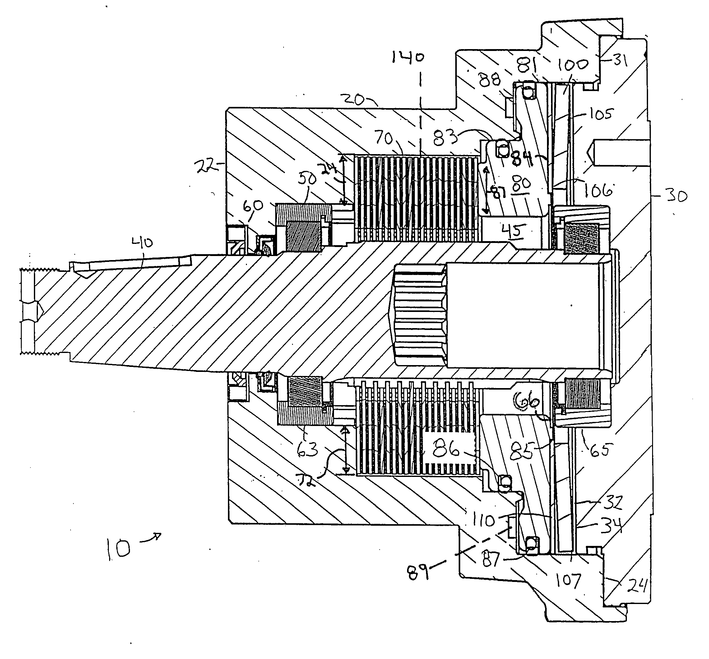
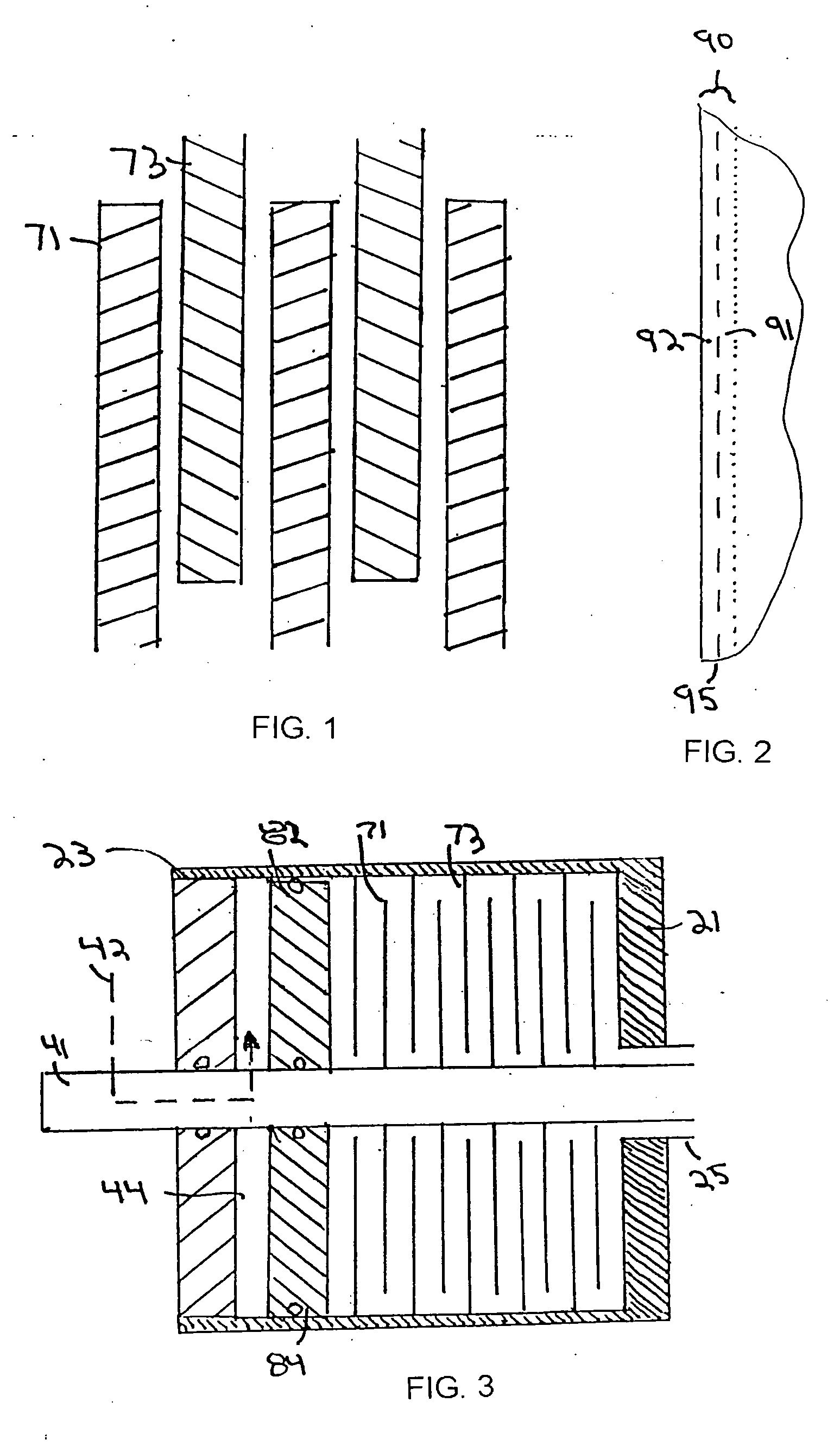
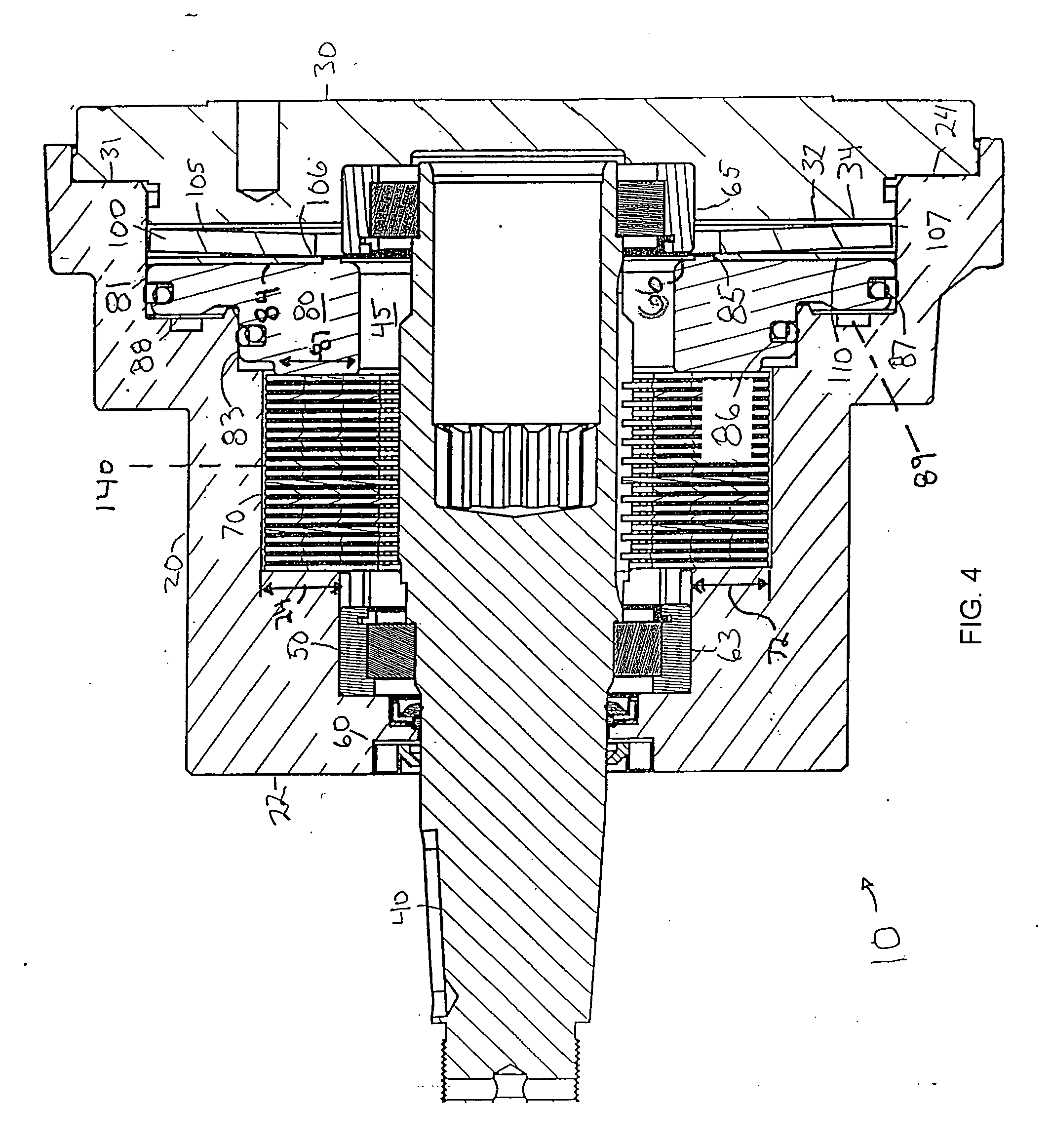
[0028] In this invention the engagement surfaces of disks in a disk pack is treated with a hardening agent to produce an integral wear surface (FIGS. 1-2). These disks are incorporated into an engagement mechanism (FIG. 3).

[0029] In the engagement mechanism at least a pair of disks 71, 73 are located adjacent to each other between an engagement mechanism 82 and a reaction surface 21. The two 81, 21 are movable in respect to each other so as to press the disks 71, 73 against each other. Since one disk 71 is drivingly connected to one part 41 while the other disk 73 is connected to another part 23, this action interconnects the two parts 41, 23 to each other. This serves as a clutch if both parts 41, 23 can rotate while serving as a brake if one part 41, 23 is relatively rotationally impeded. For example if part 23 is able to rotate at the same speed as part 41, the engagement action produces a driving connection therewith. This would result in power between 41 and 25. Additional exa...


PUM

PropertyMeasurementUnit
inner diameteraaaaaaaaaa
thicknessaaaaaaaaaa

Abstract

A selectively engageable friction mechanism such as a brake assembly including hard anodized brake disks having a single cross section and a bias assembly including a single spring, in the preferred embodiment such spring being a belleville spring

Description

[0001] This application is a continuation of U.S. patent application Ser. No. 10 / 073,520, which is incorporated by reference.BACKGROUND [0002] This invention relates to a selectively engageable friction mechanism for a brake or clutch shaft such as those typically utilized in a combination axle support and brake mechanism. BRIEF DESCRIPTION [0003] Selectively engageable friction devices for shafts have been utilized to control power in a positive mechanism (such as a motor clutch) and / or a negative mechanism (such as a brake). In some instances, the same shaft has been utilized for a secondary purpose, such as functioning as an axle (such as for a wheel) or a rotary support for a secondary member (such as a winch spool). [0004] Certain of these friction devices include interleaved pairs of disks, each pair connected to differing parts thereof. Typically these mechanisms included concentric sintered rings of a friction substance on steel disks. This additional substance significantly...

Claims


Application Information

Patent Timeline
Patent Type & Authority Applications(United States)
IPC IPC(8): F16D55/36B66D5/14F16D59/02F16D65/14
CPCB66D5/14F16D55/36F16D59/02F16D2121/12F16D2121/14F16D2250/0046
Inventor DAIGRE, RICHARD
Owner WHITE HYDRAULICS
Why Eureka
Try Eureka