

Electric Motor
- Summary
- Abstract
- Description
- Claims
- Application Information
AI Technical Summary
Benefits of technology
Problems solved by technology
Method used
Image

Examples
Embodiment Construction
[0023]Throughout this description, identical parts have always been provided with the same reference symbols in the various figures in the drawing. For this reason, any description of a part with reference to a specific figure in the drawing also applies to other figures in which the part can likewise be seen with the corresponding reference symbol.
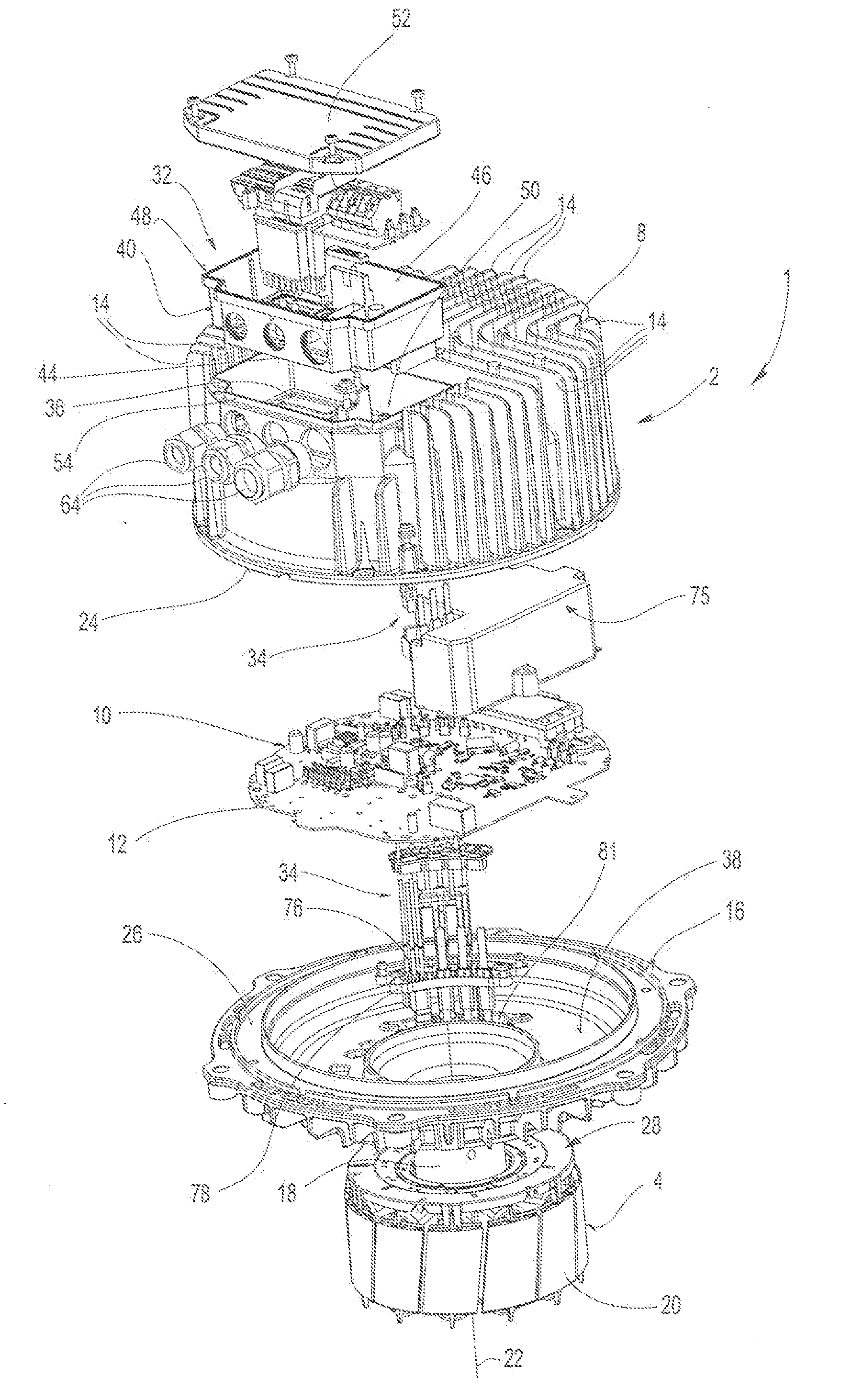
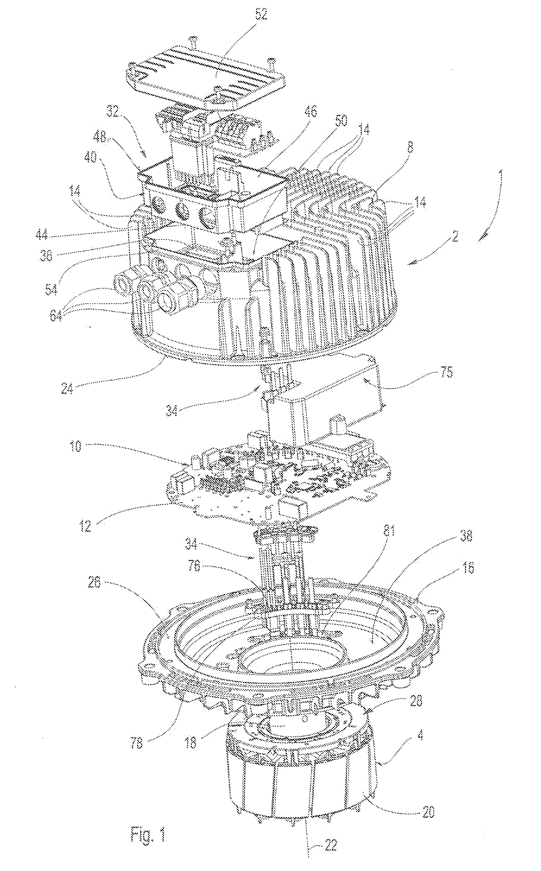
[0024]In the embodiment illustrated, an electric motor 1 according to the invention is in the form of a brush-less, electronically commutated DC external rotor motor. The electric motor 1 has an encapsulated motor housing 2 such that it satisfies a high level of IP protection in accordance with IEC 60034 5, for example IP 54.
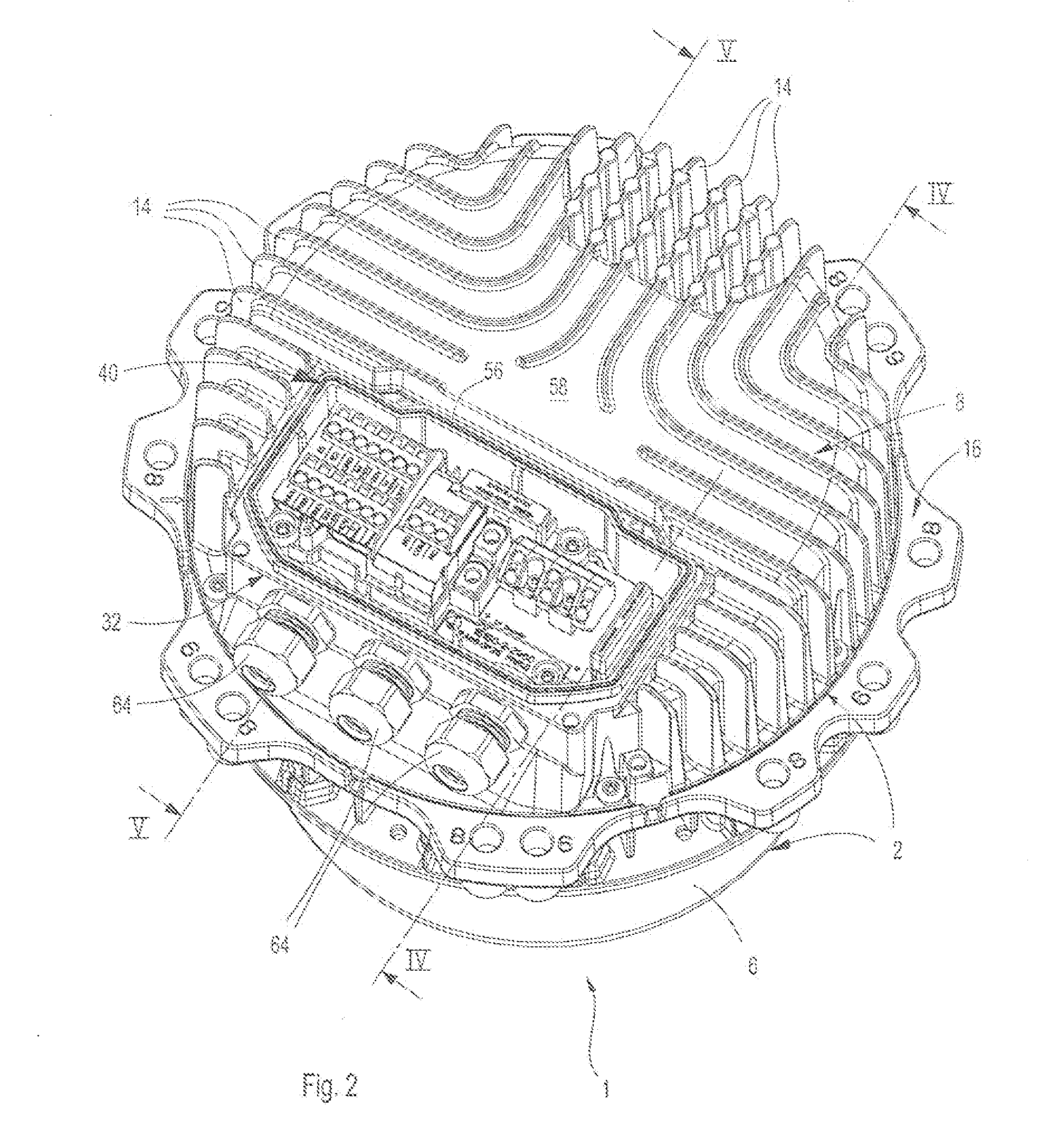
[0025]As can be seen from FIGS. 1 to 3, the electric motor 1 comprises a stator 4 (see in this regard also FIG. 8) and an external rotor 6, which surrounds the stator 4 from one side as part of the motor housing 2 in the form of a pot. This external rotor 6 is only illustrated in FIGS. 2 and 3, but not in FIGS. 1 and ...
PUM
 Abstract
Description
Claims
Application Information