Circumferential feather seal

a technology of circumferential feathers and seals, applied in the direction of engine seals, leakage prevention, engine components, etc., can solve the problems of loss of energy, adverse to fuel economy, and adverse to seals, and achieve simple seal configuration, adequate seal, and minimize fluid leakage

Inactive Publication Date: 2006-04-20
PRATT & WHITNEY CANADA CORP
View PDF10 Cites 50 Cited by
  • Summary
  • Abstract
  • Description
  • Claims
  • Application Information

AI Technical Summary

Benefits of technology

[0007] In accordance with further aspect of the present invention, there is provided a seal assembly for minimizing fluid leakage between a turbine vane assembly and a turbine static shroud assembly, the vane and shroud assemblies having planar radially-extending annular surfaces facing one another, the seal assembly comprising annular recesses defined in the respective annular surfaces, and a feather seal extending between the recesses. The feather seal preferably extends substantially around but is less than a complete circumference of the annular recesses to thereby permit interference

Problems solved by technology

It is well-known to be undesirable to have uncontrolled air leakage between the shrouds of a vane ring and an adjacent turbine static shroud because leakage is a loss

Method used


Image

  • Circumferential feather seal
  • Circumferential feather seal
  • Circumferential feather seal

Examples


first embodiment

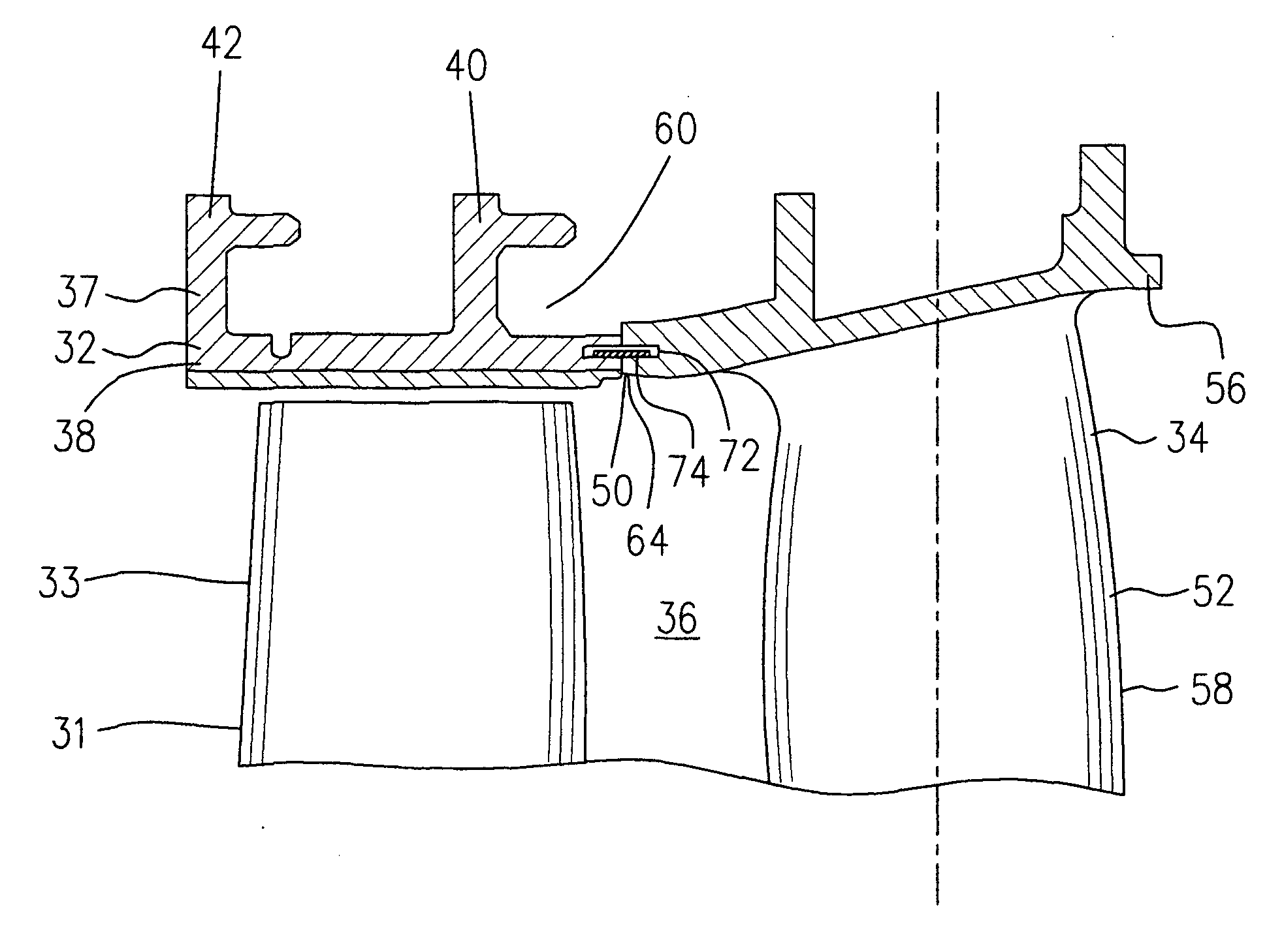
[0029] In other embodiments described below, similar parts are identified with numerals similar to those of the description of the first embodiment and will not be redundantly described.

second embodiment

[0030] The annular cavity and the seal of the present invention can be in various cross-sections. For example, in accordance with the present invention and illustrated in FIG. 5, an annular cavity 72a is formed by two annular recesses 68a, 70a which are at angles to each other. The seal 74a includes a circumferentially extending seal which is angled along a central axis (not indicated) such that the two sides thereof are angled to correspond with angled orientation of the two annular recesses 68a and 70a.

third embodiment

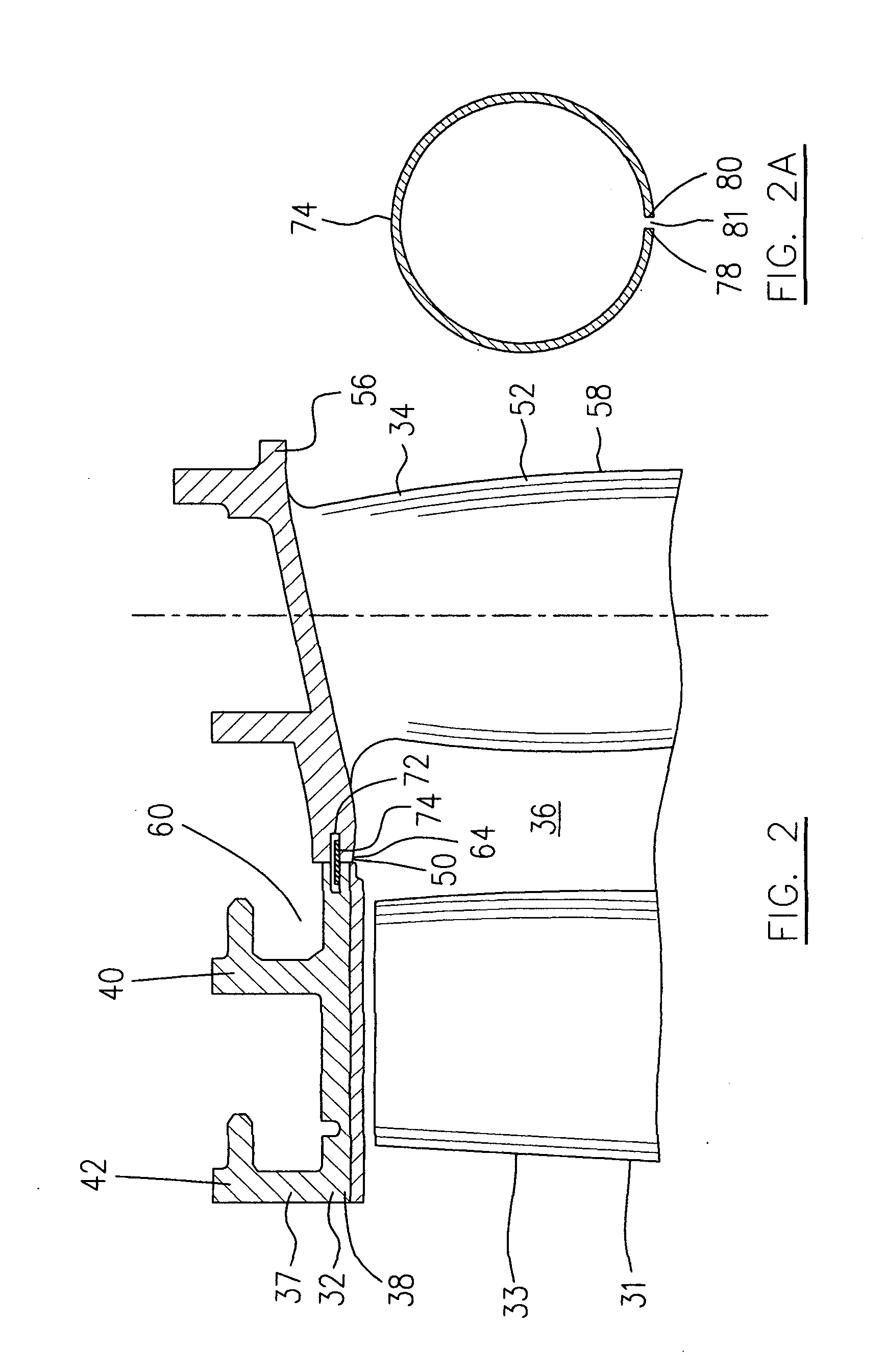
[0031]FIG. 6 illustrates the present invention in which the seal 74b includes a circumferentially extending seal having a curved cross-section such that the opposite sides 78, 80 thereof, have a diameter greater than the diameter of the middle portion therebetween.


PUM


Abstract

A seal arrangement between a vane assembly and a static shroud assembly reduces gas path leakage and beneficially improves gas turbine performance.

Description

FIELD OF THE INVENTION [0001] The present invention relates to gas turbine engines, and particularly to seal means for the air leakage existing between the outer shroud of the rotor blades and adjacent stator vane shroud. BACKGROUND OF THE INVENTION [0002] It is well-known to be undesirable to have uncontrolled air leakage between the shrouds of a vane ring and an adjacent turbine static shroud because leakage is a loss of energy and adverse to fuel economy. [0003] Various arrangements for sealing such leakages have been proposed, such as a continuous seal ring provided between successive shrouds. Due to the high temperature working condition of a gas turbine, the continuous seal ring requires a low thermal expansion in order to ensure an adequate seal. However, such a seal will be adversely affected when successive shrouds have different thermal expansions during engine operation. Therefore there is a need for improved seal means which will be more adequate under high temperature w...

Claims


Application Information

Patent Timeline
IPC IPC(8): F16J15/02
CPCF01D11/005F16J15/0887F05D2240/57
Inventor SYNNOTT, REMYGLASSPOOLE, DAVID
Owner PRATT & WHITNEY CANADA CORP
Why Eureka
Try Eureka