Liquid ejection head, liquid ejection apparatus, and image forming apparatus

a liquid ejection and liquid ejection technology, applied in the direction of printing, inking apparatus, etc., can solve the problems of insufficient application to maximize the function and density, and achieve the effect of maximizing the function and density of the head, improving the ejection efficiency, and preventing acoustic crosstalk

Inactive Publication Date: 2006-04-20
FUJIFILM CORP
View PDF6 Cites 16 Cited by
  • Summary
  • Abstract
  • Description
  • Claims
  • Application Information

AI Technical Summary

Benefits of technology

[0046] According to the present invention, since the individual electrodes of the plurality of piezoelectric elements disposed in one pressure chamber are separated, control of the drive can be performed on each element. According to this configuration, by controlling the drive phases, drive timings, drive waveforms and the like of the plurality of piezoelectric elements, and improvement of the ejection efficiency can be achieved, and control of the amount of liquid droplets to be ejected, and control of the spatter direction (ejection direction) of the liquid droplets are possible, or acoustic crosstalk can be prevented. Further, a piezoelectric element which is not driven can be utilized as a pressure determination sensor so that an ejection failure can be detected. Consequently, maximization of the function and density of the head can be realized.

Problems solved by technology

In this regard, application to maximization of the function and density is not considered sufficiently in Japanese Patent Application Publication No. 5-38809.

Method used


Image

  • Liquid ejection head, liquid ejection apparatus, and image forming apparatus
  • Liquid ejection head, liquid ejection apparatus, and image forming apparatus
  • Liquid ejection head, liquid ejection apparatus, and image forming apparatus

Examples


Embodiment Construction

Entire Configuration of Inkjet Recording Apparatus

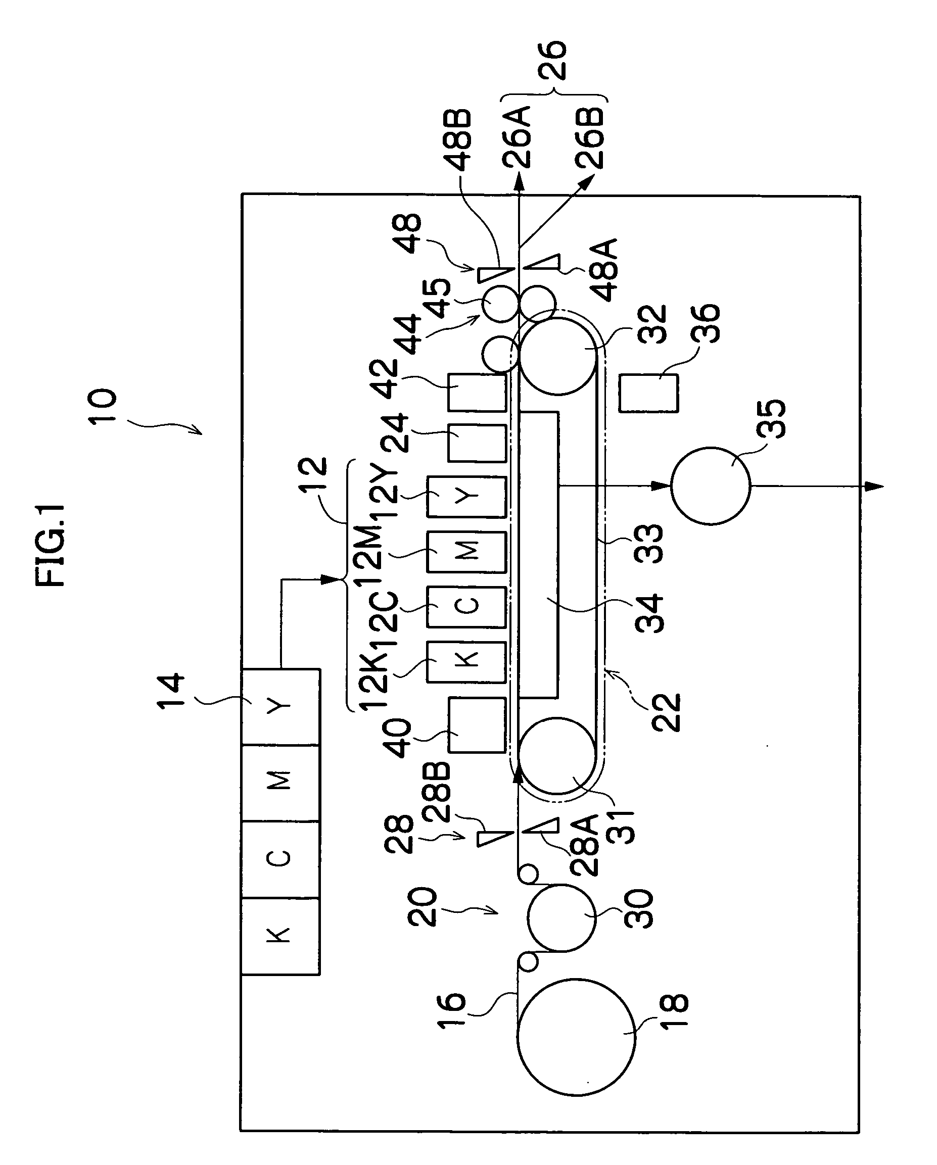
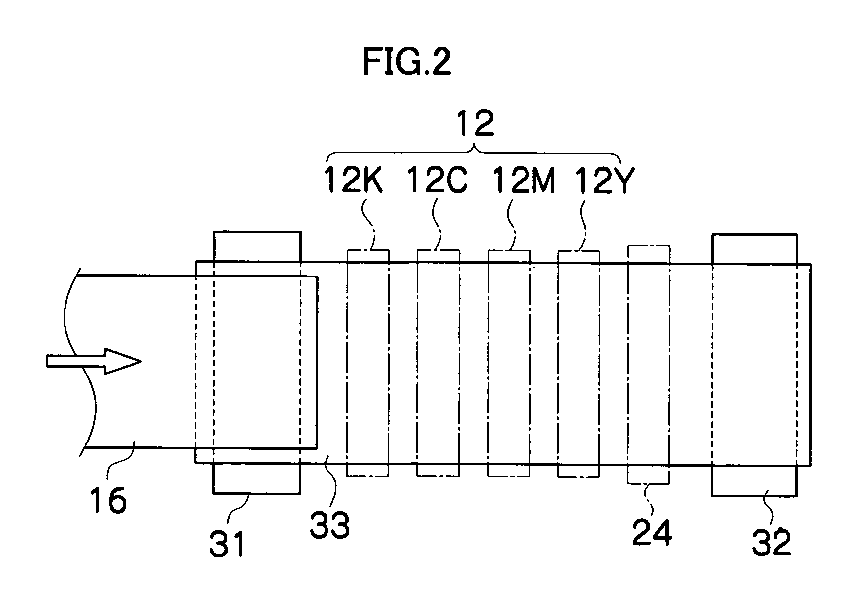
[0067]FIG. 1 is a figure of an entire configuration of an inkjet recording apparatus in which is employed the liquid ejection head according to an embodiment of the present invention. As shown in the figure, the inkjet recording apparatus 10 comprises: a printing unit 12 having a plurality of inkjet heads (referred to as heads hereinafter) 12K, 12C, 12M, and 12Y provided for ink colors of black (K), cyan (C), magenta (M), and yellow (Y), respectively; an ink storing / loading unit 14 for storing inks to be supplied to the heads 12K, 12C, 12M, and 12Y respectively; a paper supply unit 18 for supplying a recording paper 16 which is a recording medium (a medium subjected to ink ejection); a decurling unit 20 for removing curl in the recording paper 16; a suction belt conveyance unit 22 disposed facing the nozzle face (ink ejection face) of the printing unit 12, for conveying the recording paper 16 while keeping the recording paper 16 fl...


PUM


Abstract

The liquid ejection head comprises: a plurality of liquid ejection ports; a plurality of pressure chambers which are respectively communicated with the liquid ejection ports; a diaphragm which configures at least one surface of each of the pressure chambers; and a plurality of piezoelectric elements which are disposed on a surface of the diaphragm opposite from the pressure chamber, and from which at least individual electrodes are separated in an area corresponding to the pressure chamber, wherein liquid is ejected from the liquid ejection port by causing the plurality of piezoelectric elements to make vibration.

Description

BACKGROUND OF THE INVENTION [0001] 1. Field of the Invention [0002] The present invention relates to a liquid ejection head, liquid ejection apparatus, and image forming apparatus, more particularly to a structure and drive control technology of a liquid ejection head which is suitable for an image forming apparatus such as an inkjet recording apparatus for forming an image on a recording medium by ejecting minuscule liquid droplets. [0003] 2. Description of the Related Art [0004] Japanese Patent Application Publication No. 5-38809 discloses an inkjet head which generates ultrasonic wave in ink by driving, at high frequency, a piezoelectric substrate disposed in parallel with a nozzle plate, and ejects mist-like ink (ink mist) from the nozzles. Japanese Patent Application Publication No. 5-38809 further proposes disposition of a concave acoustic lens between the piezoelectric substrate and the nozzle plate in order to focus pressure wave in the vicinity of the nozzles. [0005] Howeve...

Claims


Application Information

Patent Timeline
Patent Type & Authority Applications(United States)
IPC IPC(8): B41J2/045
CPCB41J2/0451B41J2/04543B41J2/0456B41J2/04573B41J2/04581B41J2/04588B41J2/14233B41J2002/14338B41J2002/14419B41J2202/20B41J2202/21
Inventor NAGASHIMA, KANJI
Owner FUJIFILM CORP
Why Eureka
Try Eureka