Lighting apparatus having a uniform luminance profile

a technology of lighting apparatus and luminance profile, which is applied in the direction of lighting and heating apparatus, point-like light sources, instruments, etc., can solve the problems of chromaticity difference on the emission surface and consume a longer time, and achieve the effect of suppressing the uniformity of luminan

Active Publication Date: 2006-04-20
BEIHAI HKC OPTOELECTRONICS TECH CO LTD
View PDF7 Cites 5 Cited by
  • Summary
  • Abstract
  • Description
  • Claims
  • Application Information

AI Technical Summary

Benefits of technology

[0012] In view of the above problem in the conventional techniques, it is an object of the present invention to provide a lighting apparatus, which is capable of suppressing the ununiformity of the luminance without involving a chromaticity difference on the emission surface thereof.
[0015] In accordance with the present invention, the reflecting member reflects light emitted by the luminescent members toward the light diffusion plate to increase the luminance of a portion of the emission surface of the lighting apparatus in front of the gap between the luminescent members, thereby improving the luminance profile of the emission surface.

Problems solved by technology

The dot-pattern printing technique, however, involves a problem of a chromaticity difference on the emission surface due to the reflection characteristic of the ink material used for the printing.
In the techniques described in the publications, there is a problem however that the optimum profile of the rear reflection plate differs depending on the distance between the diffusion plate and the lamps, pitch of the lamps, diameters of the lamps etc., which fact consumes a longer time in the design and production of the prototype backlight units for assuring the effectiveness of the design, although the design itself may be performed using a simulation.

Method used


Image

  • Lighting apparatus having a uniform luminance profile
  • Lighting apparatus having a uniform luminance profile
  • Lighting apparatus having a uniform luminance profile

Examples


first embodiment

[0050]FIG. 7A shows a top plan view of another reflecting member 22 of a first modification modified from the reflecting member 21 of the above embodiment, and FIGS. 7B and 7C show sectional views as viewed from the directions “B” and “C” in FIG. 7A. The reflecting member 22 in this modification also has a pair of white reflecting surfaces 43a having a light scattering property and a reflectance of 97%. The mirror surface 43a has a depression in the central line as viewed in the direction normal to the extending direction of the elongate lamps 13. In the reflecting member 22, the thickness thereof linearly reduces along the direction from each side edge toward the central line. The material for the reflecting member 22 is similar to the material for the reflecting member 21 of the

[0051] In this modification, the light incident onto the mirror surfaces 43a of the reflecting member 22 is more effectively reflected from the mirror surface 43a to increase the luminance at the portion of...

third embodiment

[0067]FIG. 19 shows a portion of another reflecting member 31 of a modification modified from the The reflecting member 31 includes a slit 48 corresponding to each of the through-holes 47 receiving therein the lamps. The lamp can be inserted to the through-hole 47 via the slit 48. This reduces the manpower for assembly of the lighting apparatus.

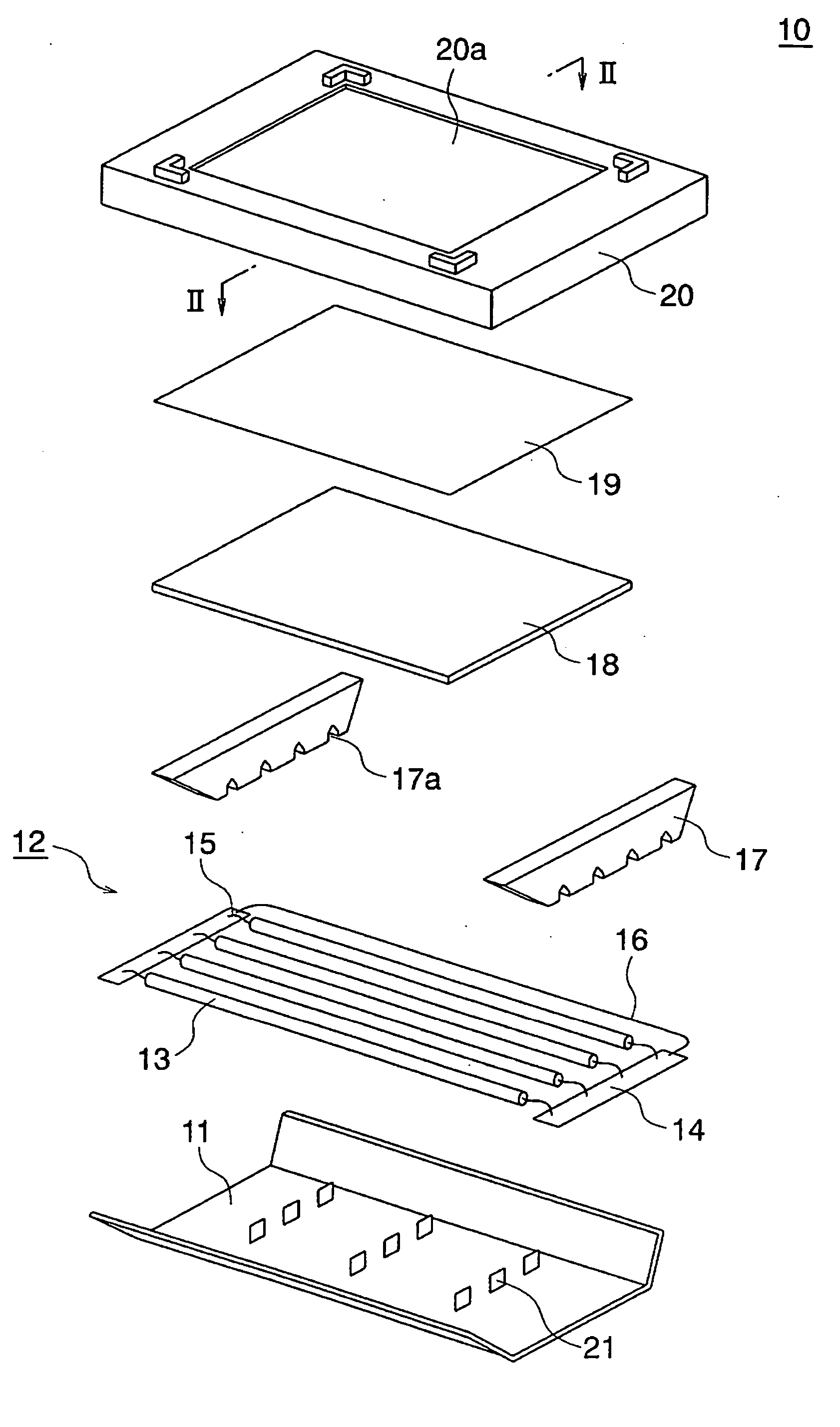
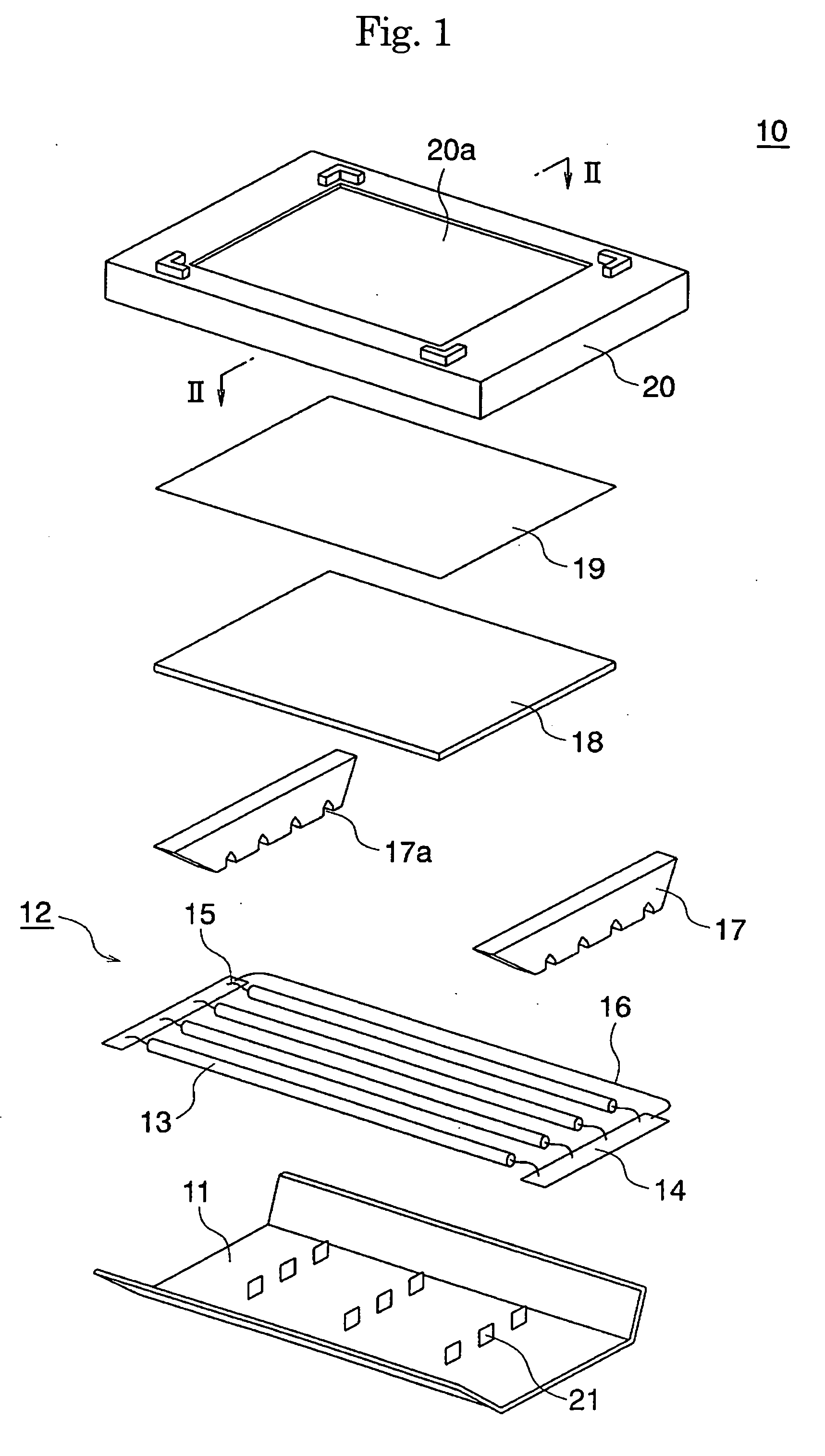
[0068]FIG. 20 shows, in an exploded perspective view, an LCD device according to a fourth embodiment of the present invention, which includes the lighting apparatus 51 of the third embodiment. The LCD device 106 is configured as a double-sided LCD device, and includes the lighting apparatus 51 of the third embodiment, a pair of LC panels 101 each disposed on one of both the emission surfaces 20a of the lighting apparatus 51, and a pair of front shields 102 for defining the housing to receive therein the LC panel 101 and the backlight unit 51. The double-sided LCD device 106 has a pair of screens 102a, which achieve a uniform luminance.

[0069...


PUM


Abstract

A direct-emission backlight unit for use in an LCD device includes a plurality of elongate lamps at the rear of a light diffusion plate and a plurality of reflecting members arranged in a matrix on a rear reflecting plate. The reflecting members are disposed in the gap between adjacent lamps, and reflect light emitted by the lamps toward the diffusion plate for achieving a uniform luminance profile of the emission surface of the backlight unit.

Description

BACKGROUND OF THE INVENTION [0001] (a) Field of the Invention [0002] The present invention relates to a lighting apparatus and a liquid crystal display (LCD) device, and more particularly, to the specific structure of a lighting apparatus and an LCD device including such a lighting apparatus as a backlight unit. [0003] (b) Description of the Related Art [0004] An LCD device known as a transmissive LCD device includes a backlight unit as a lighting apparatus for irradiating an LC panel of the LCD device from the rear side of the LC panel. The backlight unit is generally categorized into two types: direct-emission type and an edge-emission type. The direct-emission type includes a plurality of lamps at the rear of the emission surface of the backlight unit, whereas the edge-emission type includes a light conductive plate on the rear side of the emission surface of the backlight unit for guiding light emitted by a lamp. The direct-emission type achieves a higher luminance compared to t...

Claims


Application Information

Patent Timeline
Patent Type & Authority Applications(United States)
IPC IPC(8): F21V7/04
CPCG02F1/133604G02F1/133605G02F1/133611G02F1/1335
Inventor ONO, SHIN-ICHIROU
Owner BEIHAI HKC OPTOELECTRONICS TECH CO LTD
Why Eureka
Try Eureka