Compressor

a compressor and motor technology, applied in the direction of machines/engines, rotary/oscillating piston pump components, liquid fuel engines, etc., can solve the problems of deteriorating the heat exchange efficiency, affecting the efficiency of the refrigeration cycle itself, and insufficient lubrication of the mechanical sliding portion such as the compressor mechanism in the housing, so as to achieve efficient separation of lubricant oil and reduce the effect of deterioration of heat exchange efficiency

Inactive Publication Date: 2006-04-20
PANASONIC CORP
View PDF5 Cites 7 Cited by
  • Summary
  • Abstract
  • Description
  • Claims
  • Application Information

AI Technical Summary

Benefits of technology

[0018] According to the compressor of the present invention, it is possible to provide a motor-incorporated type compressor capable of efficiently separating lubricant oil from a refrigerant with a simple structure. That is, it is possible to separate the lubricant oil in a small space and to reduce the compressor in size and weight without deteriorating the separating ability of the lubricant oil. Therefore, a refrigeration cycle having higher efficiency than that of the conventional refrigeration cycle can be provided.
[0019] According to the compressor of the first aspect of the invention, the oil-reservoir chamber which is independent from the motor chamber in which the motor is accommodated is formed in the housing on the opposite side from the compressor mechanism with respect to the motor. According to this aspect, the centrifugal separation type lubricant oil separating technique can be applied to the motor-incorporated type compressor, and the lubricant oil can be separated with a simple structure.
[0020] According to the second aspect, in the compressor of the first aspect, the partition member for liquid-tightly dividing the motor chamber and the oil-reservoir chamber from each other is disposed between the motor chamber and the oil-reservoir chamber, thereby forming the oil-reservoir chamber. According to this aspect, the independent oil-reservoir chamber can easily be formed.
[0021] According to the third aspect, in the compressor of the first aspect, the partition member for liquid-tightly dividing the motor chamber and the oil-reservoir chamber from each other is disposed, and the partition member is pushed by a stator constituting the motor, thereby fixing the partition member to the housing. According to this aspect, since the partition member for liquid-tightly dividing the motor chamber and the oil-reservoir chamber from each other is fixed to the housing by pushing the partition member, it is possible to prevent the compressor structure and its assembling operation from becoming complicated.
[0022] According to the fourth aspect, the partition member for separating the oil-reservoir chamber from the compressor mechanism and the motor is provided, the partition member is provided at only its upper portion with the through hole through which the refrigerant is discharged out, the compressor mechanism and the motor are completely separated from each other at the lower portion of the partition member, and the oil passage is provided in the lower portion of the oil-reservoir chamber divided by the partition member. According to this aspect, the lubricant oil can be separated in a small space, axial direction the compressor can be reduced in size and weight. Further, the refrigerant including lubricant oil discharged from the compressor mechanism into the housing passes through the through hole formed in the upper portion of the partition member and is separated from the lubricant oil, and only the lubricant oil is stored in the lower portion of the oil-reservoir chamber. The lubricant oil which is completely separated and stored in the oil-reservoir chamber and stabilized can be supplied to the sliding portion or the like through the oil passage formed in the lower portion of the oil-reservoir chamber.
[0023] According to the fifth aspect, in the compressor of the fourth aspect, the refrigerant discharged from the through hole is allowed to collide against the portion of the housing, thereby separating the lubricant oil from the refrigerant. According to this aspect, the refrigerant which passed through the through hole collides against the housing, and the lubricant oil is separated by this collision, and the lubricant oil can be stored in the oil-reservoir chamber efficiently.

Problems solved by technology

The lubricant oil included in the refrigerant supplied into the refrigeration cycle adheres to an inner wall of a heat exchanger in the refrigeration cycle, and deteriorates the heat exchanging efficiency, and deteriorates the efficiency of the refrigeration cycle itself.
If a large amount of lubricant oil is circulated through the refrigeration cycle at the same time, there is an adverse possibility that lubrication of the mechanical sliding portion such as the compressor mechanism in the housing becomes insufficient.

Method used


Image

  • Compressor
  • Compressor
  • Compressor

Examples


first embodiment

[0029] Embodiments of a compressor according to the present invention will be explained with reference to the drawings. Technical elements explained in the following embodiments can be employed in various combinations unless such combinations violate the purpose of the invention.

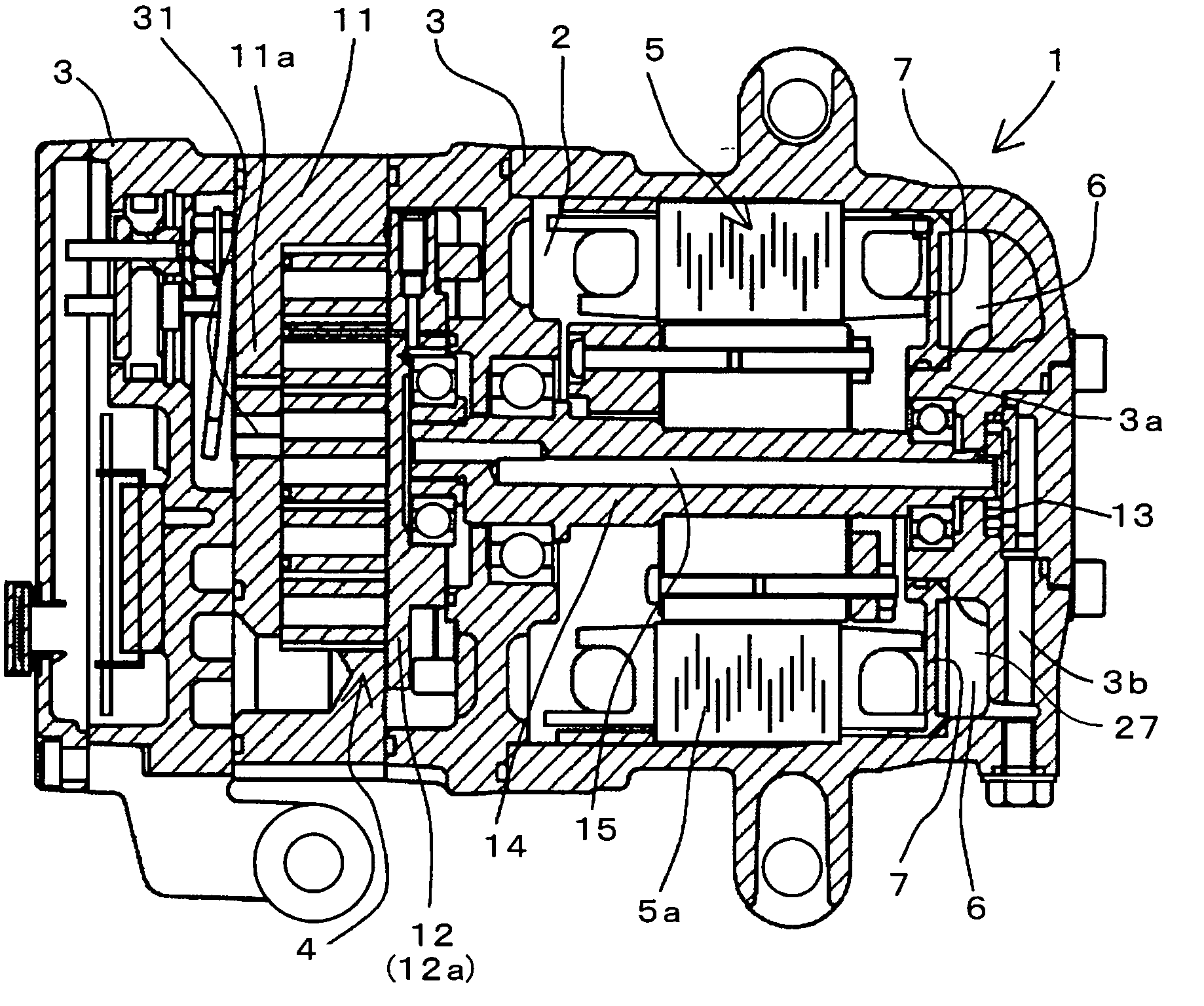
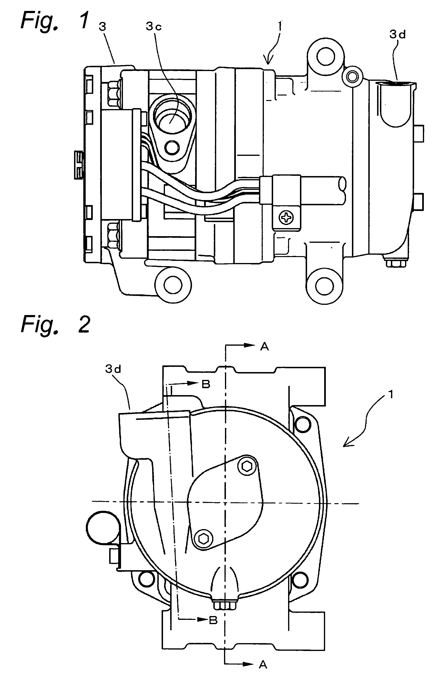
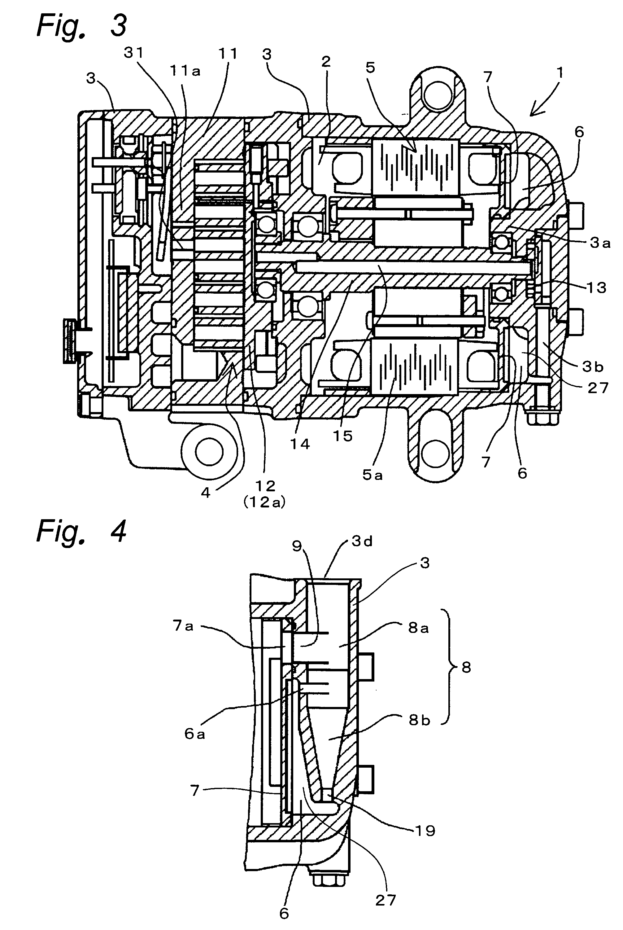
[0030]FIG. 1 is a front view of an outward appearance of a compressor according to a first embodiment of the present invention, FIG. 2 is a right side view of the outward appearance of the compressor shown in FIG. 1, FIG. 3 is a sectional view of the compressor shown in FIG. 2 taken along the line A-A, and FIG. 4 is a sectional view of the compressor shown in FIG. 2 taken along the line B-B, and FIG. 4 shows a cross section of a separation chamber in which lubricant oil included in a compressed refrigerant is separated.

[0031] The present invention is applied to a so-called horizontal type motor-incorporated compressor of the embodiment shown in the drawings which is disposed such that a rotation center axi...

second embodiment

[0043]FIG. 5 is a sectional view of a compressor according to a second embodiment of the present invention.

[0044]FIG. 5 shows one example of a horizontal type electric compressor which is disposed horizontally using mounting legs 20 provided around a body of the compressor 1.

[0045] The compressor 1 of the second embodiment has the housing 3 in which the compressor mechanism 4 and the motor 5 for driving the compressor mechanism 4 are accommodated. The lubricant oil 27 used for lubricating sliding portions including the compressor mechanism 4 is stored in the oil-reservoir chamber 6. The motor 5 is driven by a motor drive circuit (not shown). Gas refrigerant is used as the refrigerant. The lubricant oil 27 is used for lubricating the sliding portions and also used for sealing the sliding portions of the compressor mechanism 4. Lubricant oil having compatibility with respect to the refrigerant is used as the lubricant oil 27.

[0046] The compressor is not limited to the compressor 1 ...


PUM


Abstract

It is an object of the present invention to make an oil-reservoir chamber independent from a motor chamber into which a refrigerant compressed by a compressor mechanism is introduced, thereby reducing a compressor in size. In a compressor 1, a partition member 7 is provided in a housing 3 on the opposite side from a compressor mechanism 4 with respect to a motor 5. The partition member 7 is pushed by a stator 5a of the motor 5, thereby liquid-tightly fixing the partition member 7 to the housing 3. The oil-reservoir chamber 6 is formed independently from a motor chamber 2 in which the motor 5 is accommodated, and lubricant oil is efficiently separated from a refrigerant with a simple structure.

Description

TECHNICAL FIELD [0001] The present invention relates to a motor-incorporated type compressor having a housing in which a compressor mechanism for sucking, compressing and discharging a refrigerant, and a motor for driving the compressor mechanism are accommodated, and more particularly, to a liquid separating apparatus of a compressor having an oil-reservoir chamber for storing lubricant oil therein. BACKGROUND TECHNIQUE [0002] The compressor of this kind is actually utilized as a compressor for a domestic room air conditioner and a refrigerator. Recently, such a compressor is also utilized as a compressor for an air conditioner for an automobile. [0003] In such a compressor, if the compressor mechanism is driven by the incorporated motor, a refrigerant in a refrigeration cycle is sucked through a suction port in the housing, the refrigerant is compressed and is discharged into the housing and then, the refrigerant is supplied to the refrigeration cycle from a discharge port of the ...

Claims


Application Information

Patent Timeline
Patent Type & Authority Applications(United States)
IPC IPC(8): F01C1/02F04C2/00F01C1/063F04C18/00
CPCF04C23/008F04C29/026
Inventor MAKINO, MASAHIKOOGAWA, NOBUAKIFUJIWARA, YUKIHIROFUKUMOTO, MINORUTAGUCHI, TATSUHISA
Owner PANASONIC CORP
Why Eureka
Try Eureka