Intervertebral implant

a technology of intervertebral implants and implants, which is applied in the field of intervertebral implants, can solve the problems of limiting the anterior movement without a greater risk to the surrounding structure, and achieve the effect of less stress

Active Publication Date: 2006-04-20
AO TECH AG +1
View PDF99 Cites 444 Cited by
  • Summary
  • Abstract
  • Description
  • Claims
  • Application Information

AI Technical Summary

Benefits of technology

[0006] The present invention is to provide a remedy for the above-discussed disadvantages. The present invention is directed to an intervertebral implant which can enter into a permanent, rigid connection with bone fixation means, so that, even if the bone structure is weakened, there is no loosening between the intervertebral implant and the bone fixation means. Moreover, over a separately constructed front plate, there is tension chording for the bone fixation elements, so that the implant body experiences less stress, that is, superimposed tensions. Moreover, a securing plate enables all bone fixation elements to be secured simultaneously.
[0008] Compared to the two-part implants of the state of the art, for which a front plate is implanted in a separate step, the present invention has the advantage that the implantation of the intervertebral implant may be carried out in one step and, with that, can be carried out more easily and more quickly. A further advantage is that the intervertebral implant is fixed as frontally as possible at the body of the vertebra. That is, at a place where good bone material usually is present. The result is an anterior movement limitation without a greater risk to the surrounding structures. The load is still absorbed under compression by the intervertebral implant and not by the front plate or the fixation screws (longitudinal fixation elements).

Problems solved by technology

The result is an anterior movement limitation without a greater risk to the surrounding structures.

Method used


Image

  • Intervertebral implant
  • Intervertebral implant
  • Intervertebral implant

Examples


Embodiment Construction

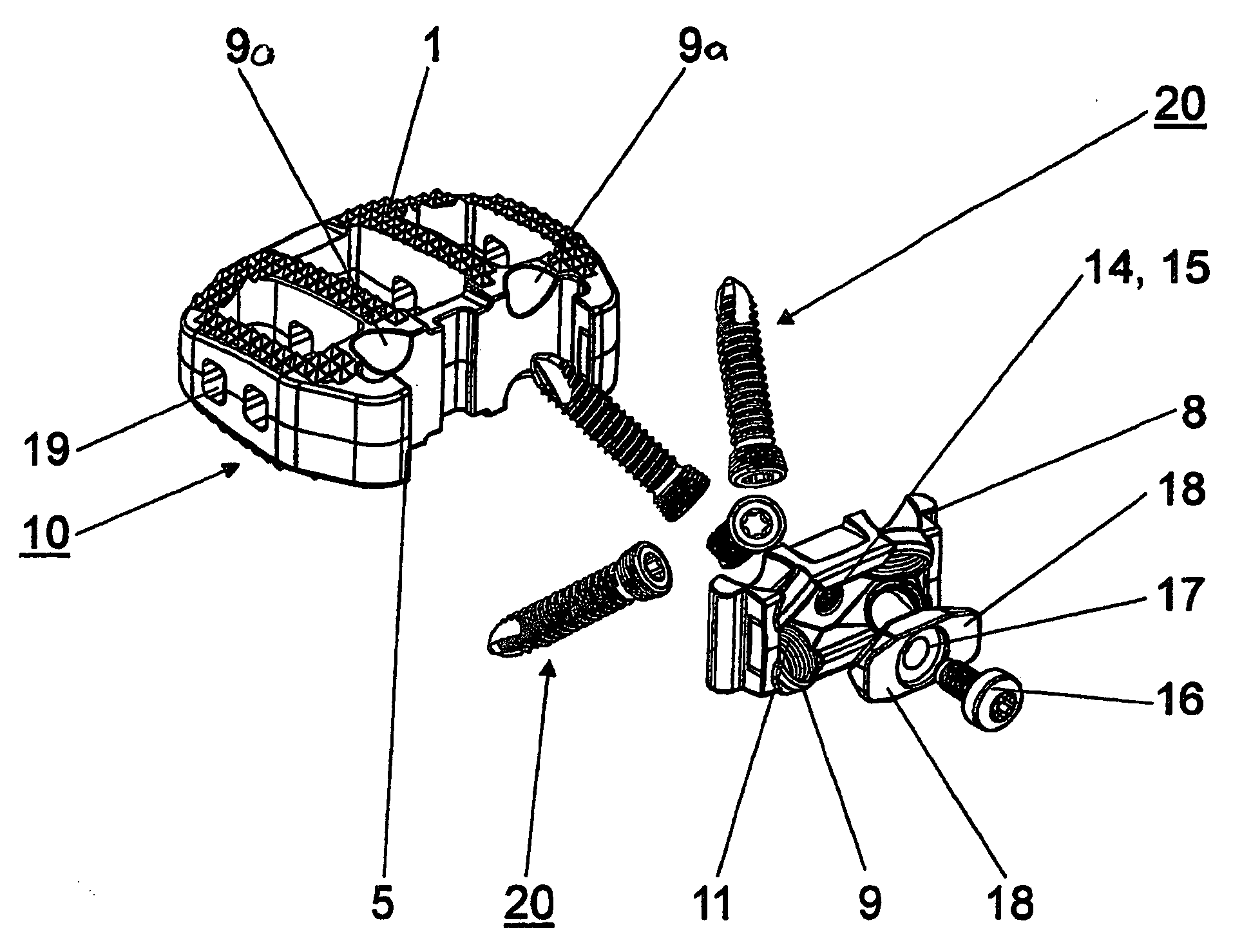
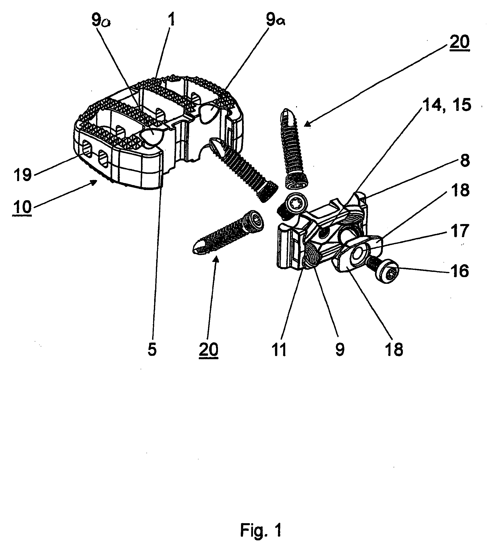
[0018] The intervertebral implant, shown in FIG. 1-7, includes a three-dimensional body 10 in the form of a cage with an upper side 1 and an underside 2, which are suitable for abutting the end plates of two adjacent vertebral bodies, a left side surface 3 and a right side surface 4, a front surface 5 and a back surface 6, a horizontal middle plane 7 located between the upper side 1 and the underside 2, a vertical middle plane 12 extending from the front surface 5 to the rear surface 6 and four boreholes 9a, which pass through the body 10 and are suitable for accommodating longitudinal fixation elements 20. The body 10 may be constructed as a hollow body, the mantle surfaces of which are provided with perforations 19. The upper side 1 and / or under side 2 of the intervertebral implant may preferably be convex in shape, not planar. A convex shape to the upper side 1 and the underside 2 allows for an improved fit with the end plates of the adjacent vertebral bodies by the intervertebra...


PUM


Abstract

An intervertebral implant having a three-dimensional body (10) and a securing plate (1). The three-dimensional body (10) includes an upper side (1) and an underside (2) which are suitable for abutting the end plates of two adjacent vertebral bodies, a left side surface (3) and a right side surface (4), a front surface (5) and a rear surface (6), a horizontal middle plane (7) between the upper side (1) and the underside (2), and a vertical middle plane (12) extending from the front surface (5) to the rear surface (6). The three-dimensional body further includes a plurality of boreholes (9a) passing through the body (10), which are suitable for accommodating longitudinal fixation elements (20). The intervertebral implant also includes a front plate (8) displaceably disposed as an insert with the front side (5) of the three-dimensional body, the front plate (8) having a plurality of boreholes (9) in which the longitudinal fixation elements (20) can be anchored, and whose openings overlap with the openings of the boreholes of the three-dimensional body (10). A securing plate can be fastened essentially parallel to the front plate (8) at the three-dimensional body (10) in such a manner that the boreholes of the front plate (9) are covered at least partly by the securing plate (18). By virtue of the configuration of the intervertebral implant, a rigid, firm connection between the intervertebral implant and the longitudinal fixation elements used to fasten it, is possible.

Description

CROSS REFERENCE TO RELATED APPLICATION [0001] This application is a continuation of International Patent Application No. PCT / CH2003 / 000089, filed Feb. 6, 2003, the entire contents of which is expressly incorporated herein by reference.TECHNICAL FIELD [0002] The present invention relates generally to intervertebral implants. BACKGROUND OF THE INVENTION [0003] GB-A-2 207 607 discloses an intervertebral implant, which has a horseshoe-shaped configuration with a plurality of cylindrical holes. The holes are smooth on the inside and only have a stop for the heads of the bone screws, which are to be introduced therein. A disadvantage of this arrangement is that the fastening screws, introduced therein, can be anchored only with their shaft in the bone. This does not result in a rigid connection with the horseshoe-shaped intervertebral implant. When the anchoring of the screw shaft in the bone is weakened, the intervertebral implant becomes movable with respect to the screw and the bone sc...

Claims


Application Information

Patent Timeline
Patent Type & Authority Applications(United States)
IPC IPC(8): A61F2/44A61B17/86A61F2/00A61F2/30
CPCA61B17/86A61F2/442A61F2/4455A61F2002/30383A61F2002/30426A61F2310/00023A61F2002/30517A61F2002/30774A61F2002/30777A61F2002/30843A61F2220/0025A61F2002/305A61F2/4465A61F2002/30593
Inventor LECHMANN, BEATBURKARD, DOMINIQUECAIN, CHRIS M.J.MATHIEU, CLAUDE
Owner AO TECH AG
Why Eureka
Try Eureka