Oscillating Inertial Microbalance and Method of Passive Compensation

a technology of inertial microbalance and mass measurement device, which is applied in the direction of material analysis using wave/particle radiation, instruments, specific gravity measurement, etc., can solve the problems of difficult to precisely determine the application of temperature correction, the mass measurement of material deposited on the oscillating inertial microbalance may be adversely affected, and the instrument used to measure a particular parameter may be affected by the variation of other parameters. , to achieve the effect of minimizing energy transfer and minimizing

Active Publication Date: 2006-04-27
SIERRA INSTR
View PDF3 Cites 13 Cited by
  • Summary
  • Abstract
  • Description
  • Claims
  • Application Information

AI Technical Summary

Benefits of technology

[0030] Further, the two elastic oscillating elements can be mounted in such a way as to minimize energy transfer from one elastic oscillating element to the other elastic oscillating element. Consider two elastic oscillating elements mounted in the same plane as compared to those oscillating in orthogonal planes. It will be clear to those skilled in the art that an orthogonally mounted system will minimize the energy transfer between the two elastic oscillating elements.

Problems solved by technology

It is difficult to precisely determine how to apply corrections for temperature when the adverse effects are comprised of those from the fluid properties of the sampled gas and those errors contributed by a change in the modulus of elasticity of the oscillating element has with temperature.
Further, instruments used to measure a particular parameter may be affected by the variation of other parameters.
For example, measurement of the mass of material deposited on an oscillating inertial microbalance may be adversely affected by a variation in temperature and / or pressure and / or changes in modulus of elasticity of the oscillating element of the oscillating inertial microbalance.
The resulting increase in the mass of the filter results in a decrease of the resonant frequency of the oscillating element.
They are not designed to remove the sensitivities an inertial microbalance has to the modulus of elasticity with temperature and the density change within the hollow oscillating element as a result of temperature and pressure.
None of these patents provide for a continuous indication of the mass in near real time.
Instead, they require that the particulate laden sample stream be interrupted, the results of which result in the disruption of the sampling cycle which can in turn potentially lead to the missing of an episode wherein a large concentration of the particulate sample is ignored.
As the measured mass is based on the resonant frequency, an error is introduced in the mass determination.
In the end, compromises must be made at the expense of the accuracy, manufacturability and cost of the entire system.
Both of these patents fail to completely address the adverse effects of temperature sensitivity having to do with the modulus of elasticity of the oscillating element.
The dual sensor system fails to subject both oscillators to substantially the same conditions.
However, the first and second detectors are not of a geometry capable of addressing the additional problem of the density change of the fluid within the hollow oscillating element and therefore can not compensate for these effects.
Neither of these two aforementioned patents adequately addresses the adverse effects of indicating a mass because both subject the “reference” resonator to a change in state resulting from the collection of a “clean” sample.

Method used


Image

  • Oscillating Inertial Microbalance and Method of Passive Compensation
  • Oscillating Inertial Microbalance and Method of Passive Compensation
  • Oscillating Inertial Microbalance and Method of Passive Compensation

Examples


Embodiment Construction

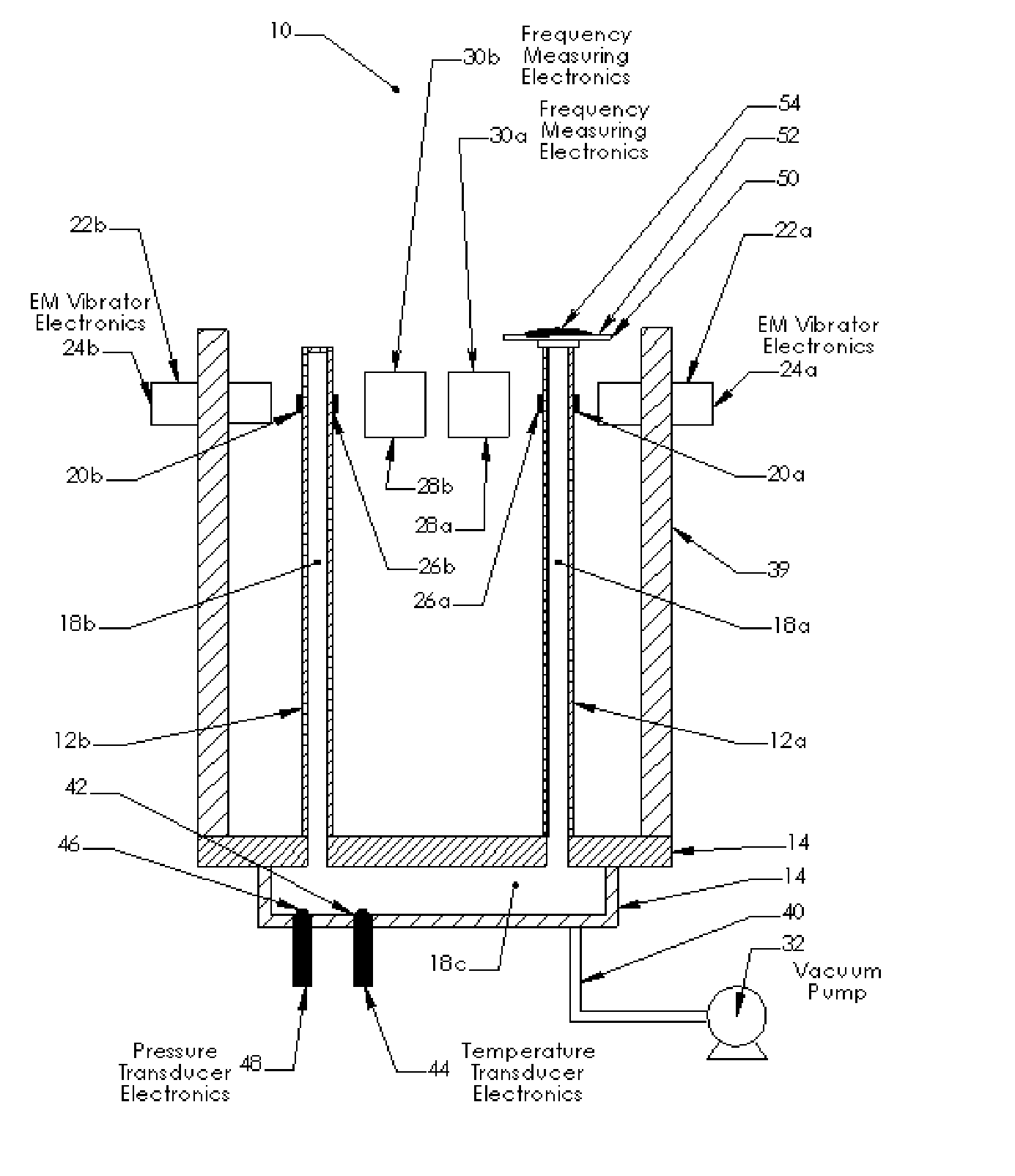
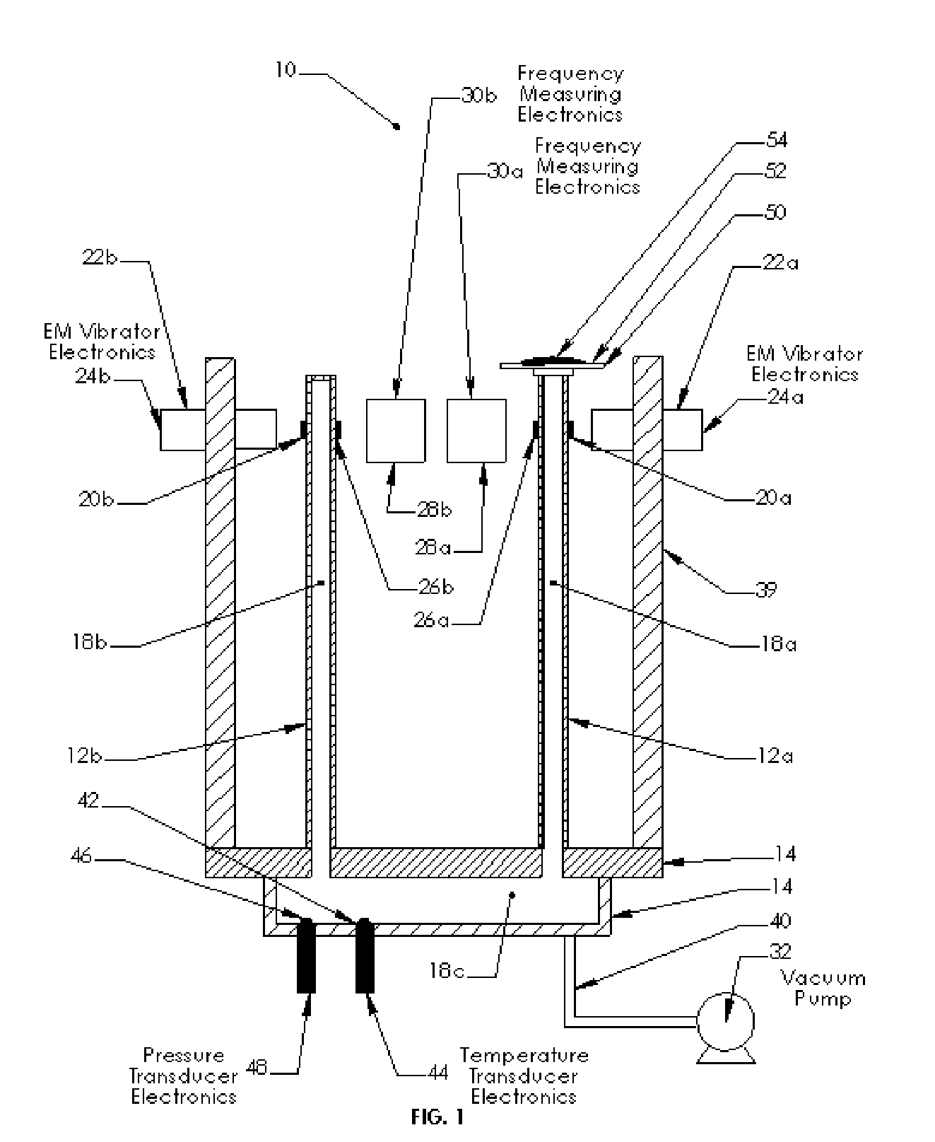
[0041] The present invention provides for a passive method and apparatus which overcomes problems found in the prior art.

[0042] In several embodiments of the present invention there is no need to utilize complex methods and or formulae for the heat treatment of the oscillating element as illustrated in U.S. Pat. No. 6,080,939. Additionally, schemes such as those in U.S. Pat. No. 6,080,939 sport elastic oscillating elements with “low” thermoelastic coefficients that are not sufficiently “low” enough to support the accuracy and resolution requirements of the subject invention. It is therefore important to select a material that exhibits low losses of energy per unit oscillation. Such systems are said to have a “High Q”, and provide for a passive means of removing the effects of a non zero thermoelastic coefficient.

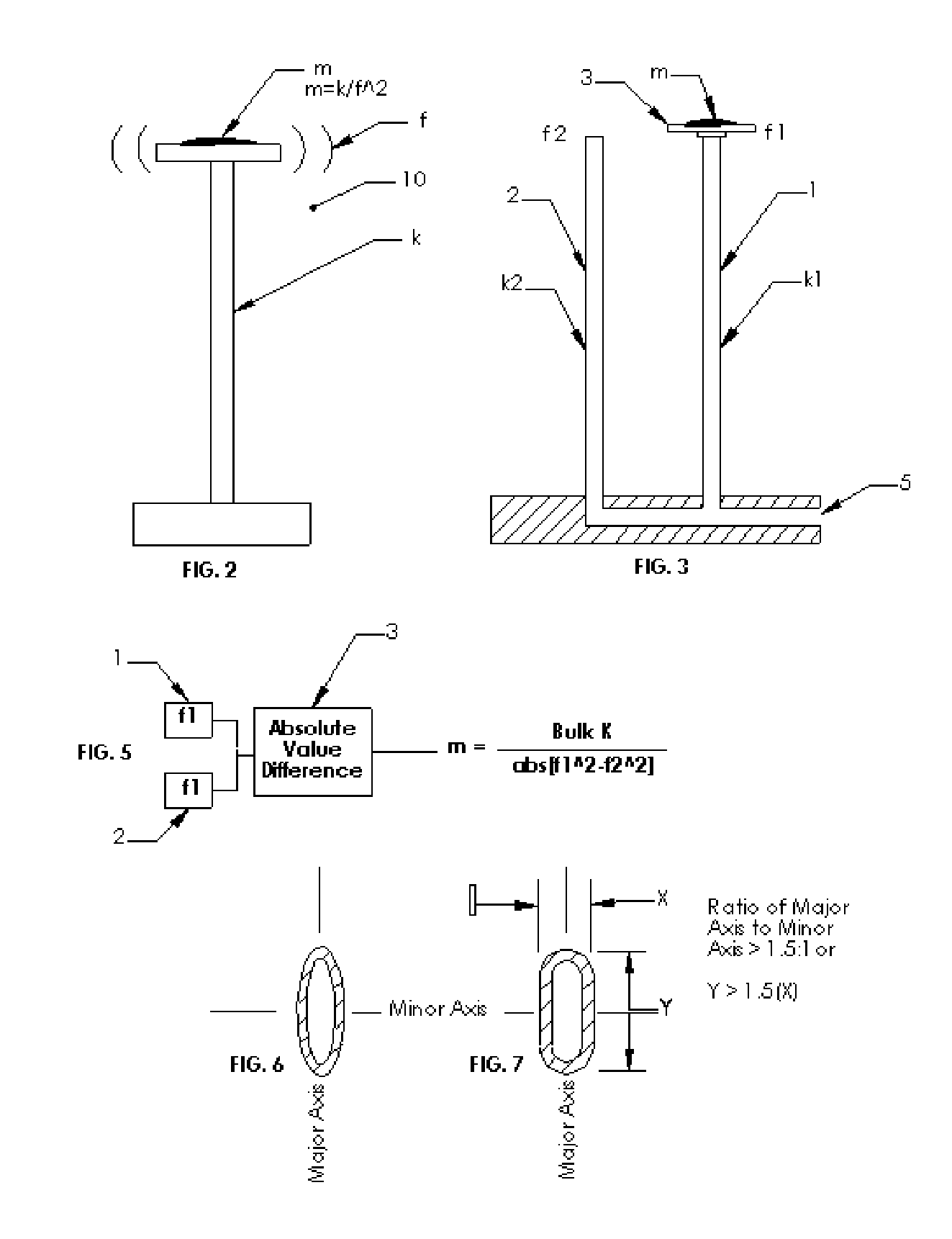
[0043] The present invention significantly reduces the temperature sensitivity by utilizing a differential mode wherein two or more resonators are utilized and only one is...


PUM

PropertyMeasurementUnit
frequencyaaaaaaaaaa
frequencyaaaaaaaaaa
frequencyaaaaaaaaaa

Abstract

The claimed subject matter is directed to a continuous passive temperature, ressure, modulus of elasticity, and force compensated oscillating inertial microbalance and method of using the same. Temperature and / or pressure and / or modulus of elasticity compensation and / or force compensation is achieved by providing two substantially similar oscillating elements wherein only one oscillating element is subjected to the mass collection means. The other oscillating element is subjected to all other factors but does not include a particulate collection means. By taking the difference between the two similar oscillating elements one can substantially remove the undesirable side effects having to do with changing temperature and / or pressure and / or modulus of elasticity. The ratio of the major axis to the minor axis is described as being important to eliminate and or minimize precession of the oscillating elements.

Description

BACKGROUND OF INVENTION [0001] This invention relates to oscillating inertial microbalance mass measurement devices and, more specifically, to mass measurement devices that reduce the adverse effects that temperature, pressure, force, and modulus of elasticity have on the true indication of mass. It is known in the art that vibrating systems have a large dependency on their environment, materials of construction, and method of manufacturing. [0002] A significant contribution to the adverse effects can come from a non-ideal oscillating element that is at the heart of the classical oscillating inertial microbalance. Exemplary construction and operation of such oscillating inertial microbalance mass measurement devices are disclosed in U.S. Pat. Nos. 4,391,338, 6,444,927, and 6,784381 which patents hereby are incorporated herein by reference in their entirety. [0003] An ideal oscillating element is one that has the ability to indicate the mass of the collected matter without the need t...

Claims


Application Information

Patent Timeline
Patent Type & Authority Applications(United States)
IPC IPC(8): G01N29/02
CPCG01G3/13G01G23/48G01N29/036G01N29/12G01N29/323G01N29/326
Inventor KORPI, DAVID MICHAEL
Owner SIERRA INSTR
Why Eureka
Try Eureka