Method and device for keeping a number of spray nozzles in a printing press beam clean

a technology of printing press and spray nozzle, which is applied in the direction of spray nozzles, printing presses, rotary presses, etc., can solve the problems of difficult to avoid the formation of printing ink mist and other matters in and around the press, certain problems in the operation of the press, and the gradual deterioration of the intended spray function

Inactive Publication Date: 2006-04-27
BALDWIN JIMEK
View PDF9 Cites 5 Cited by
  • Summary
  • Abstract
  • Description
  • Claims
  • Application Information

AI Technical Summary

Benefits of technology

[0015] The purpose of the spray casing 4 is to keep the fountain solution properly confined but also to prevent printing ink mist and other contaminants from reaching the spray nozzles 3.

Problems solved by technology

It is also well known in the art that at the high speed rotation of the different rollers in the printing press, it is difficult to obviate the formation of a mist of printing ink and other matters in and around the press.
The printing ink also causes certain problems in the operation of the press.
The printing ink mist causes clogging of the spray nozzles of the spray beam, so that their intended spray function gradually deteriorates and the spray pattern of the spray beam is changed.

Method used


Image

  • Method and device for keeping a number of spray nozzles in a printing press beam clean
  • Method and device for keeping a number of spray nozzles in a printing press beam clean
  • Method and device for keeping a number of spray nozzles in a printing press beam clean

Examples


first embodiment

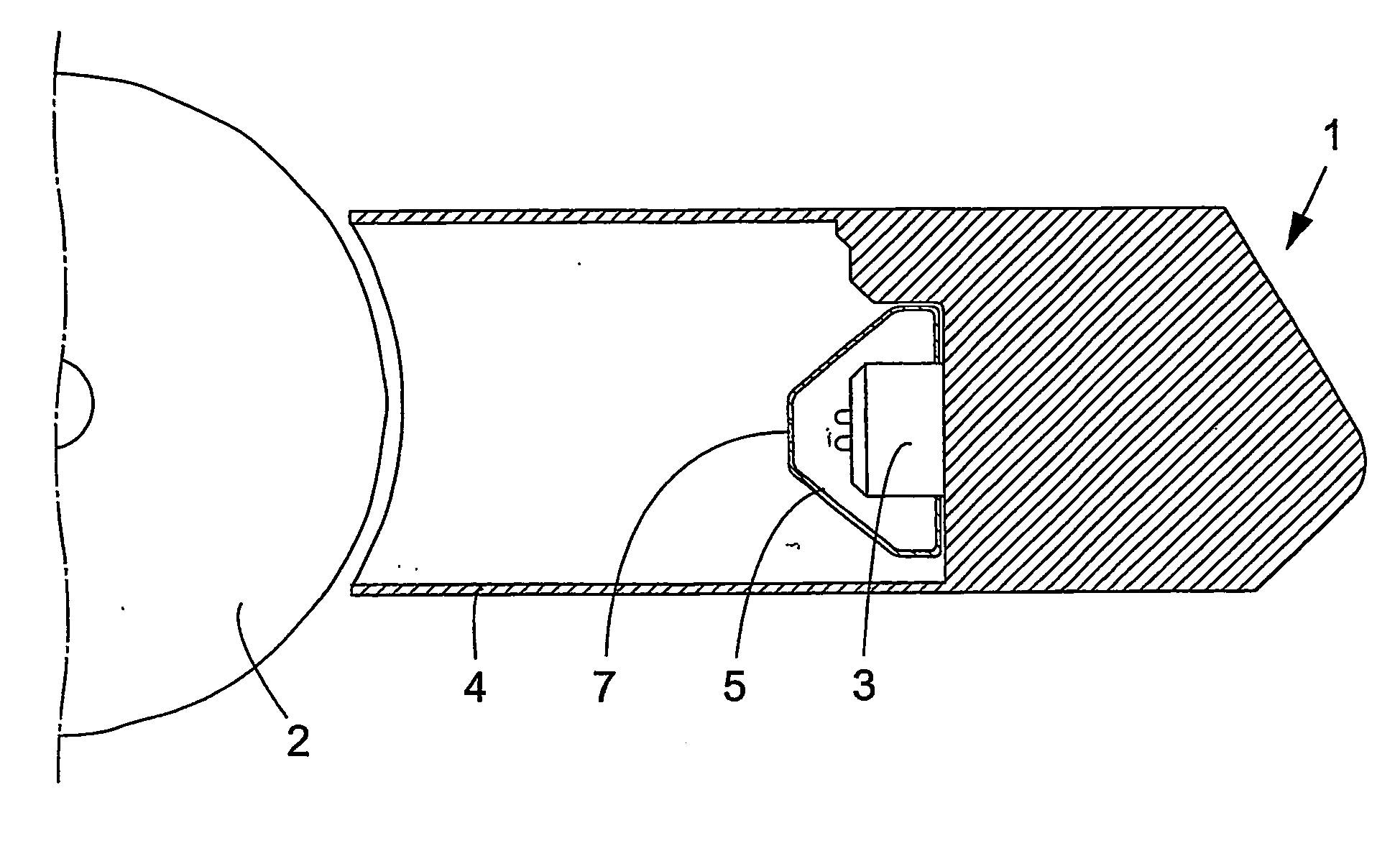
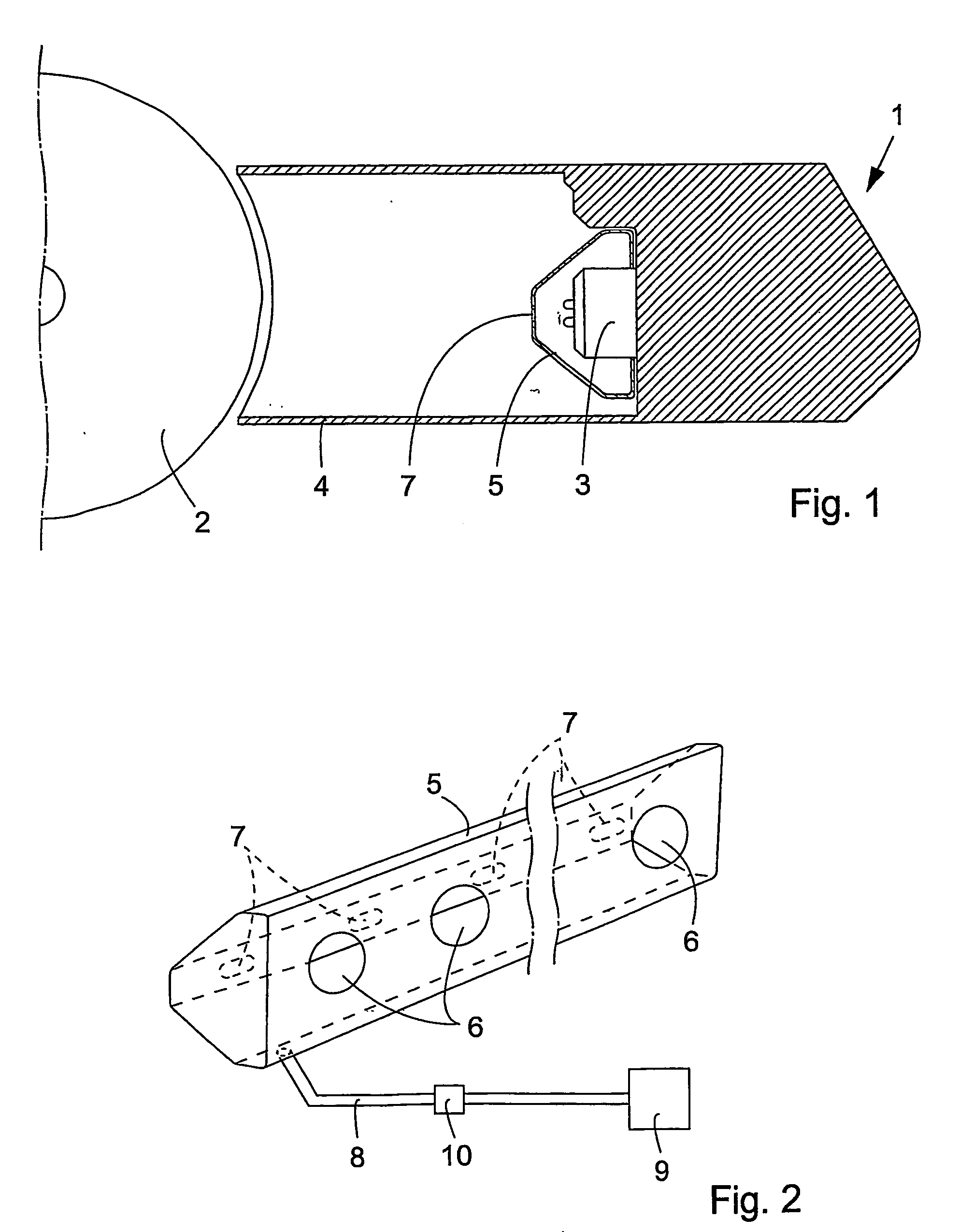
[0018]FIGS. 1 and 2 show a device for this purpose.

[0019] An elongated, generally closed cover 5 is mounted over all the spray nozzles 3 on the spray beam 1. The cover 5 can be formed of stainless steel plate or the like, but the choice of material is of no significance for the invention. The cover 5 is provided in its back wall with openings 6 for the spray nozzles 3 and in its front wall with oblong holes or slots 7 enabling the spray cones from the spray nozzles 3 to leave the cover 5 undisturbed.

[0020] Clean air with a certain overpressure is supplied to the interior of the cover 5 by means of an air conduit 8 from a main valve with a pressure regulator 9 and a throttle valve 10 for controlling the air flow. In order to obtain the desired result, several air conduits8 from the throttle valve 10 may be evenly distributed over the length of the cover 5. It may possibly be desired to provide the bottom of the cover 5 with a number of drainage holes (not shown).

[0021] The air will...

second embodiment

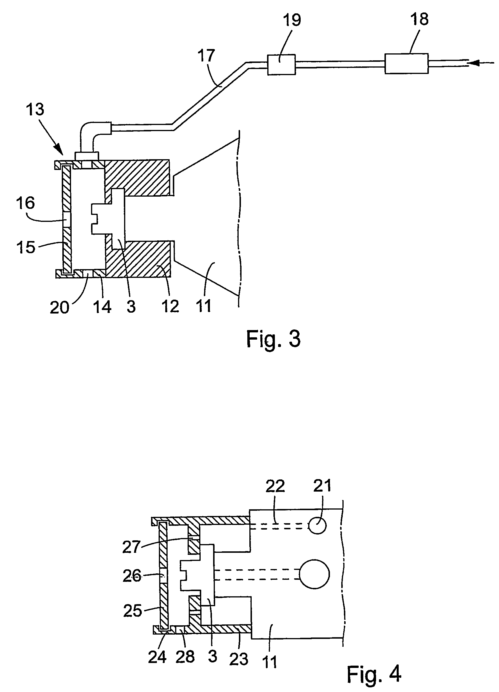
[0022] A second embodiment is shown in FIG. 3. Each spray nozzle 3 is connected to its spray valve 11 in the spray beam 1 by means of a cap 12, which may be made of a plastic material.

[0023] A cover 13 is individually provided for each spray nozzle 3. In the present case it has the form of a short sleeve 14, connected in a way not shown (but possibly by means of a bayonet joint) to the cap 12 and possibly made of a plastic material, and an end plate 15 inserted in a circumferential groove in the end of the sleeve 14. The end plate 15 has an oblong slot 16 for the spray cone from the spray nozzle 3 to pass through.

[0024] An air conduit 17 for the supply of clean air with a certain overpressure is connected to the sleeve 14. The air conduit 17 can be provided with a main valve with a pressure regulator 18 and a throttle valve 19 for controlling the air flow. The members 18 and 19 may be common for several air conduits 17 to several spray nozzles 3. Means may be provided in the cover ...


PUM


Abstract

In order to keep a spray nozzle (3) in a printing press spray beam (1) clean, air with a certain overpressure is supplied to a cover (5; 13; 24) surrounding the spray nozzle (3), the spray cone from the spray nozzle leaving the cover undisturbed through a slot (7; 16; 26) therein.

Description

TECHNICAL FIELD [0001] The present invention relates to a method and device for keeping a spray nozzle in a printing press spray beam clean. BACKGROUND OF THE INVENTION [0002] A spray beam is arranged in the proximity of a printing press roller for spraying fountain solution thereon. This fountain solution is needed for obtaining the intended printing function in the printing press, as is well known in the art. (Other liquids than fountain solution could alternatively be sprayed.) [0003] It is also well known in the art that at the high speed rotation of the different rollers in the printing press, it is difficult to obviate the formation of a mist of printing ink and other matters in and around the press. The printing ink also causes certain problems in the operation of the press. [0004] The printing ink mist causes clogging of the spray nozzles of the spray beam, so that their intended spray function gradually deteriorates and the spray pattern of the spray beam is changed. [0005]...

Claims


Application Information

Patent Timeline
Patent Type & Authority Applications(United States)
IPC IPC(8): B41L25/00B05B15/02B05B15/55B41F7/30
CPCB41F7/30B05B15/025B05B15/55
Inventor HANSSON, BIRGERARNDT, PETER
Owner BALDWIN JIMEK
Why Eureka
Try Eureka