Injection nozzle having constant diameter pin and method for operating the injection nozzle

a technology of injection nozzle and constant diameter pin, which is applied in the direction of combustion process, spray nozzle, lighting and heating apparatus, etc., can solve the problems of inability to optimize the design of the spray cone, the difficulty of adjusting the spray cone, and the comparatively high cost of the swirl passage, so as to achieve the effect of greatly improving the forming of the spray con

Active Publication Date: 2013-10-29
ANSALDO ENERGIA SWITZERLAND AG
View PDF12 Cites 5 Cited by
  • Summary
  • Abstract
  • Description
  • Claims
  • Application Information

AI Technical Summary

Benefits of technology

[0010]Another aspect of the present invention includes that a pin, which extends in the axial direction, is concentrically arranged in the inner chamber of the injection nozzle, which pin passes through the region of the mouths of the inlet ports and extends right into the nozzle orifice. In the center of the inner chamber, the pin promotes swirl of the fuel which is introduced tangentially through the inlet ports. At the same time, the pin narrows the nozzle orifice to an annular gap, by which the forming of the spray cone is greatly improved.

Problems solved by technology

In the case of the swirl chamber, the spray cone can only be adjusted with difficulty.
Furthermore, the production of the swirl passages is comparatively costly.
Both lead to a non-optimized design of the spray cone which, moreover, has a limited cone angle.

Method used


Image

  • Injection nozzle having constant diameter pin and method for operating the injection nozzle
  • Injection nozzle having constant diameter pin and method for operating the injection nozzle
  • Injection nozzle having constant diameter pin and method for operating the injection nozzle

Examples


Embodiment Construction

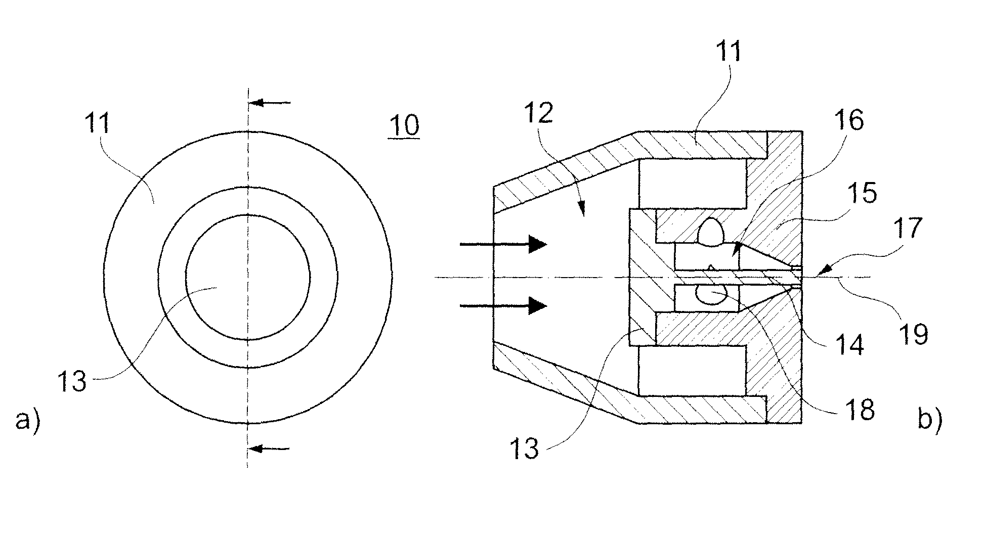
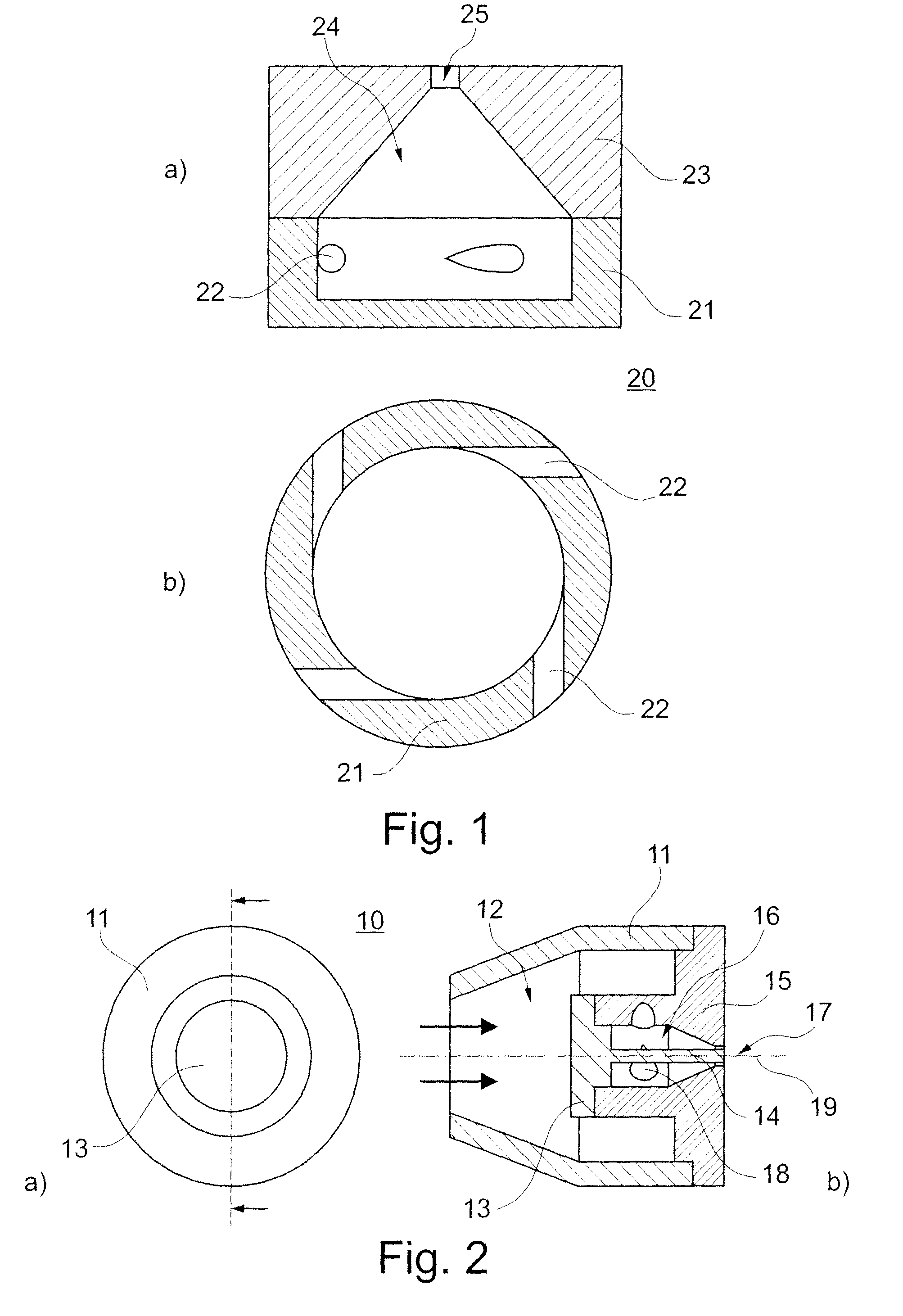
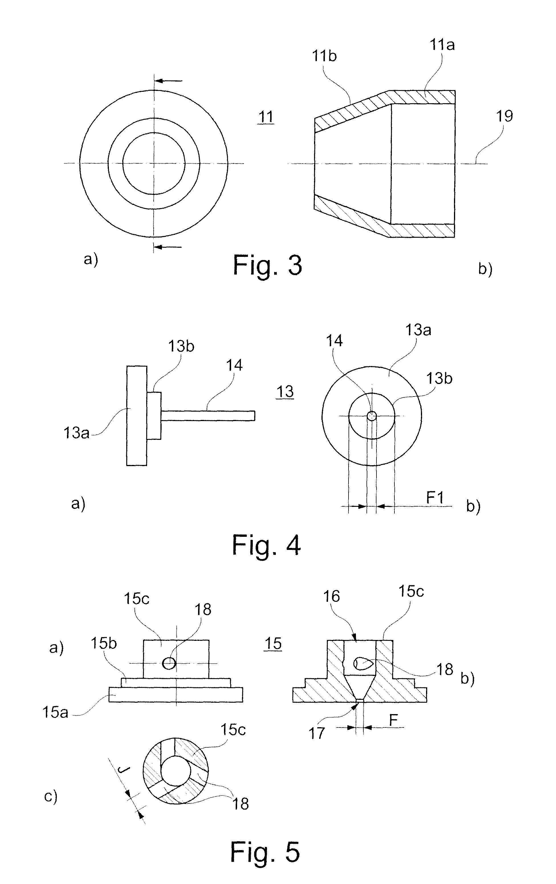
[0034]In FIG. 1, in longitudinal section (FIG. 1a) and in lateral cross section (FIG. 1b), the construction of an injection nozzle with inner chamber is reproduced, as is the starting point of nozzles embodying principles of the present invention. The injection nozzle 20 is assembled from a rear section 21 and a front section 23 which abut against each other and therefore define an inner chamber 24. The inner chamber 24 includes a cylindrical section, which is arranged in the rear section 21, and a conically tapering section which is accommodated in the front section 23. The pointed end of the conical section merges into a circular nozzle orifice 25 through which pressurized liquid fuel in the form of a spray cone can discharge outwards.

[0035]The fuel is introduced into the inner chamber 24 from outside through four inlet ports 22 which lie in one plane and lead tangentially into the inner chamber 24. The tangential orientation of the inlet ports 22 ensures that the fuel which flows...


PUM


Abstract

An injection nozzle (10), especially for injecting liquid fuel, preferably crude oil, into the combustion chamber of a gas turbine, includes an inner chamber (16) which extends along a nozzle axis (19), conically tapers to a concentric nozzle orifice (17), and to which the medium which is to be injected is fed from outside through a plurality of inlet ports (18) which are arranged in a distributed manner around the nozzle axis (19). The inlet ports (18) are oriented perpendicularly to the nozzle axis (19) and each lead tangentially into the inner chamber (16). With such an injection nozzle, an improved spray cone is achieved by the fact that a pin (14), which extends in the axial direction, is concentrically arranged in the inner chamber (16) and passes through the region of the mouths of the inlet ports (18) and extends right into the nozzle orifice (17).

Description

[0001]This application claims priority under 35 U.S.C. §119 to Swiss application no. 00105 / 10, filed 29 Jan. 2010, the entirety of which is incorporated by reference herein.BACKGROUND[0002]1. Field of Endeavor[0003]The present invention relates to the field of combustion technology, especially in connection with gas turbines. It relates to an injection nozzle and to a method for operating such an injection nozzle.[0004]2. Brief Description of the Related Art[0005]For the atomizing injection of liquid fuel into the combustion chamber of a gas turbine, a multiplicity of various injection nozzles, which differ with respect to their internal construction and the type of spray cone which is generated, are known from the prior art.[0006]A fuel nozzle with swirl passage, which includes a sleeve and a pin, is known, for example, from WO 2009 / 095100. The pin is arranged in the sleeve so that the inner surface of the sleeve is connected in a positive manner to the outer generated surface of t...

Claims


Application Information

Patent Timeline
Patent Type & Authority Patents(United States)
IPC IPC(8): B05B1/26B05B1/34
CPCB05B1/06B05B1/3426F23D11/24F23D11/383
Inventor MAGNI, FULVIONOWAK, DARIUSZDOBSKI, TOMASZSLEFARSKI, RAFAL
Owner ANSALDO ENERGIA SWITZERLAND AG
Why Eureka
Try Eureka