Manual reset switch cover assembly

Inactive Publication Date: 2006-04-27
HILLMAN KENNETH BRAD
View PDF4 Cites 2 Cited by
  • Summary
  • Abstract
  • Description
  • Claims
  • Application Information

AI Technical Summary

Benefits of technology

[0008] Broadly stated, one aspect of the present invention is a cover assembly for a device operated at least in part by a button switch, comprising a cover housing having a device side and an exterior side, said device side further comprising means for attaching to said device, said housing adapted to cover said button switch; said housing having an exterior bore extending from said exterior side partially through said housing towards said device side, and having an interior bore coaxially aligned with said exterior bore extending from said device side towards said exterior side until abutting said exterior bore, said interior bore having a larger diameter than said exterior bore whereby the junction of said bore forms a shoulder; a rod having an exterior end and an interior end, said interior end larger in diameter than said exterior end, said exterior end adapted to slidably mount in said exterior bore and said interior end adapted to slidably mount in said interior bore when said rod is inserted exterior end first into said bores from said device side whereby said shoulder prevents said rod from sliding all the way through said bores to said exterior side; an exterior cap mounted on the exterior end of said rod, said exterior cap having a peripheral edge extending radially outward beyond said rod, the combination of said exterior cap and said rod having a limited degree of longitudinal travel; biasing means disposed between the peripheral edge of said exterior cap and said exterior side of said housing for resisting longitudinal movement of said exterior cap towards said housing; and a bumper mounted on the interior end of said rod extending towards said button switch, said bumper made of a resilient and flexible material whereby upon force being applied to said exterior cap sufficient to overcome the resistance of said biasing means and push said rod towards said button switch, said bumper activates said button switch, said bumper adapted to impart sufficient force on said button switch to activate said button switch while deforming upon contact with said button switch thereby preventing excessive force from being applied to and damaging said button switch, said bumper retracting from said button switch and substantially returning to its undeformed shape upon said force being removed from said exterior cap.
[0009] Broadly stated, another aspect of the present invention is a cover assembly for a device operated at least in part by a button switch, comprising: a cover housing having a device side and an exterior side, said device side further comprising means for attaching to said device, said housing adapted to cover said button switch; said housing having a bore extending from said device to said exterior side; a plunger slidably mounted in said bore, said plunger having an exterior cap attached to the exterior end of said plunger and biasing means disposed between said exterior cap and said exterior side of said housing for resisting longitudinal movement of said plunger towards said button switch; a first stop on the exterior side of said housing to limit the longitudinal movement of said plunger towards said device side; a second stop on the device side of said housing to limit the longitudinal movement of said plunger towards said exterior side; and a bumper mounted on the interior end of said plunger extending towards said button switch, said bumper made of a resilient and flexible material whereby upon force being applied to said exterior cap sufficient to overcome the resistance of said spring and push said plunger towards said button switch, said bumper activates said button switch, said bumper adapted to impart sufficient force on said button switch to activate said button switch while deforming upon contact with said button switch thereby preventing excessive force from being applied to and damaging said button switch, said bumper retracting from said button switch and substantially returning to its undeformed shape upon said force being removed from said exterior cap.
[0010] Broadly stated, another aspect of the present invention is a cover assembly for mounting on a pressure switch having a reset button, said cover assembly having a housing and a rod extending longitudinally through said housing towards a reset button when said cover assembly is mounted on a pressure switch, said rod having exterior and interior ends and further having limited longitudinal movement with the housing, said cover assembly being characterized in that: a bumper is mounted on the interior end of said rod; and said bumper being sufficiently flexible whereby upon force being applied to said rod such that said bumper contacts a reset button of a pressure switch when said cover assembly is mounted on a pressure switch, said bumper will deform upon contacting said reset button thereby preventing excessive force from being applied to and damaging said reset button.

Problems solved by technology

In operation, it is not uncommon that excessive force is used in depressing the rod on the cap assembly to activate the reset switch.
This excessive force often physically breaks the reset switch mechanism.

Method used


Image

  • Manual reset switch cover assembly
  • Manual reset switch cover assembly
  • Manual reset switch cover assembly

Examples


Embodiment Construction

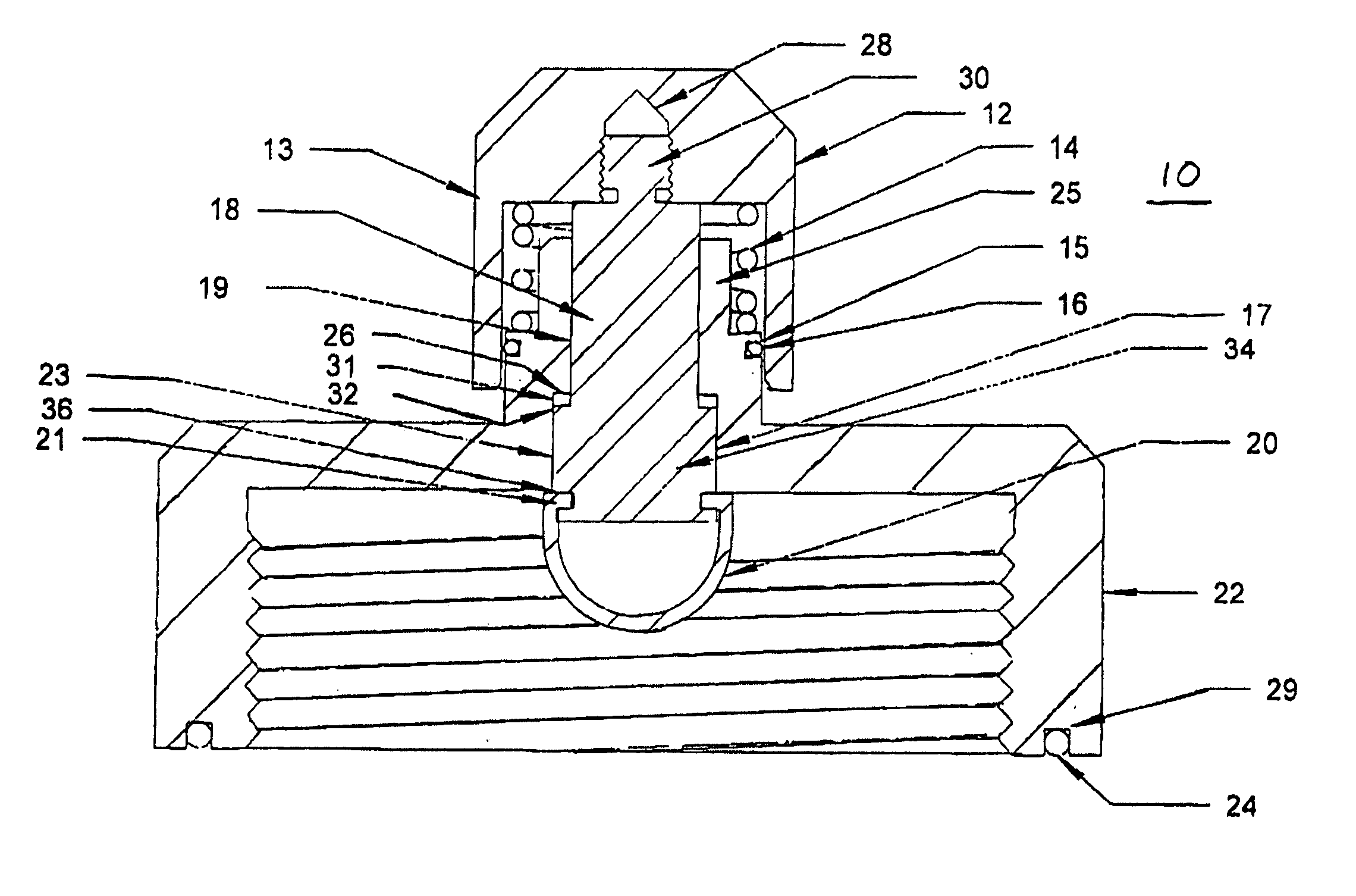
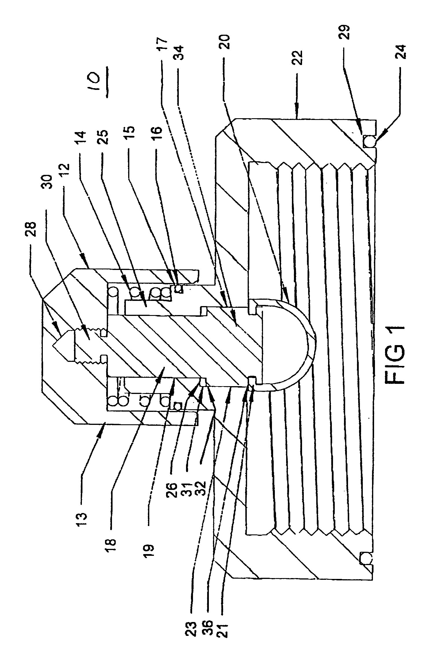
[0015] Referring to FIG. 1, manual reset switch cover assembly 10 is shown. Assembly 10 comprises of housing 22 having interior bore 23 and exterior bore 19. Exterior bore 19 is smaller in diameter than interior bore 23. The two bores are coaxially aligned thereby forming housing shoulder 26. Slidably mounted in bores 19 and 23 is rod 17.

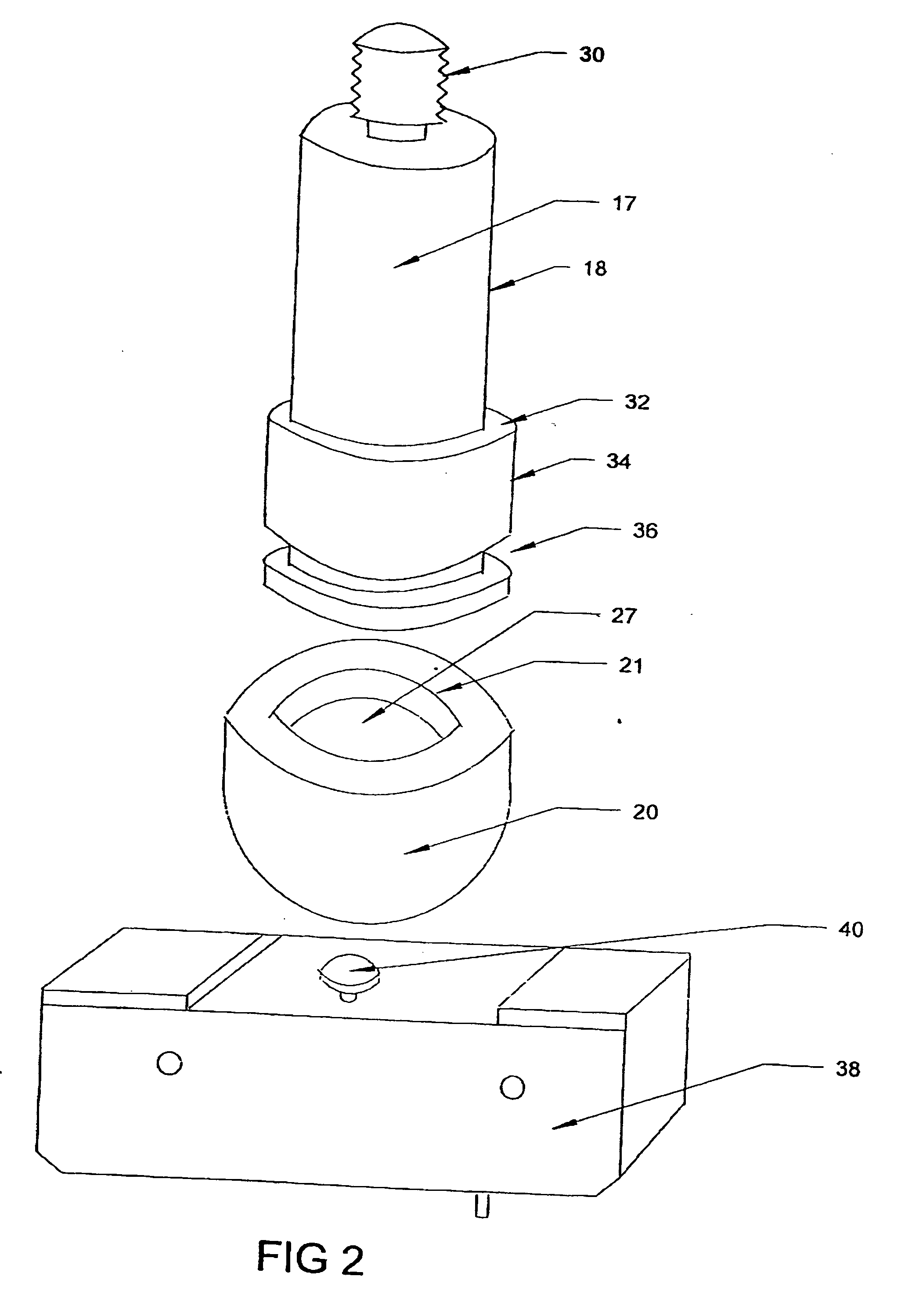
[0016] Rod 17 comprises interior end 34, which is slightly smaller in diameter than interior bore 23, and exterior end 18, which is slightly smaller in diameter than exterior bore 19. The junction of interior and exterior ends 34 and 18 form rod shoulder 32. When rod 17 is inserted exterior end first into the bores from the interior or device side of housing 22, the combination of housing shoulder 26 and rod shoulder 32 acts as a stop to prevent rod 17 from sliding all the way through housing 22 to the exterior.

[0017] On exterior end 18 of rod 17 is threaded end 30 that threads into bore 28 of cap 12. Cap 12 further comprises skirt 13 and extends ...


PUM


Abstract

The present invention is concerned with cover assemblies for manually resetting pressure switches used on oil and gas pipelines. The cover assembly encloses a volume of space on the pressure switch that houses a reset switch which is activated by depressing a button located on top of the reset switch. The cover assembly has a housing with a rod or plunger extending through the housing. On the exterior end of the rod is a protective cap and on the interior is a flexible rubber hemispherical bumper. A spring disposed between the cap and the exterior side of the cover housing biases the bumper away from the button on the reset switch. In operation, the cap is pushed towards the housing causing the rod or plunger to advance towards and contact the reset switch button. The bumper deforms or balloons outward upon contact with the button so as to impart sufficient force to depress the button but not so much force so as to damage or break the reset switch itself. When the cap is released, the spring moves the bumper away from the reset switch allowing the bumper to return to its original shape.

Description

FIELD OF THE INVENTION [0001] The present invention relates to cover assemblies for manually operating reset switches, specifically, reset switches mounted on pressure switches used on oil and gas pipelines. BACKGROUND OF THE INVENTION [0002] Pressure switches used on oil and gas pipelines operate on a change of the fluid pressure flowing through the pipeline. These pressure switches often have manual reset mechanisms that are activated by a rod which passes through a cap assembly attached to the pressure switch itself. The rod is pushed in towards the reset switch located under the cap assembly to depress a button on the reset switch. Such mechanisms are described in Canadian patents 2,129,290 and 2,178,401. In operation, it is not uncommon that excessive force is used in depressing the rod on the cap assembly to activate the reset switch. This excessive force often physically breaks the reset switch mechanism. [0003] It is, therefore, desirable to have a cover assembly for manuall...

Claims


Application Information

Patent Timeline
IPC IPC(8): H01H13/70
CPCH01H13/14H01H2221/062H01H2221/064
Inventor HILLMAN, KENNETH BRAD
Owner HILLMAN KENNETH BRAD
Why Eureka
Try Eureka