Method of friction stir welding and retractable shoulderless variable penetration friction stir welding tool for same

a friction stir and welding tool technology, applied in the field of friction stir welding, can solve the problems of pin b>92/b> being permanently lodged in the weld, finding very limited commercial application to date, and leaving an exit hole, so as to reduce internal voids and eliminate the primary source of overheating

Active Publication Date: 2006-04-27
EDISON WELDING INSTITUTE INC
View PDF14 Cites 80 Cited by
  • Summary
  • Abstract
  • Description
  • Claims
  • Application Information

AI Technical Summary

Benefits of technology

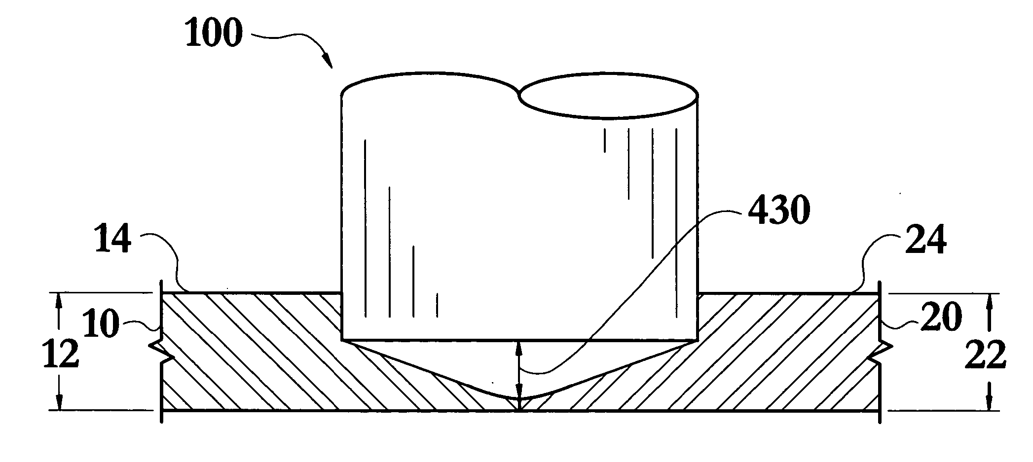
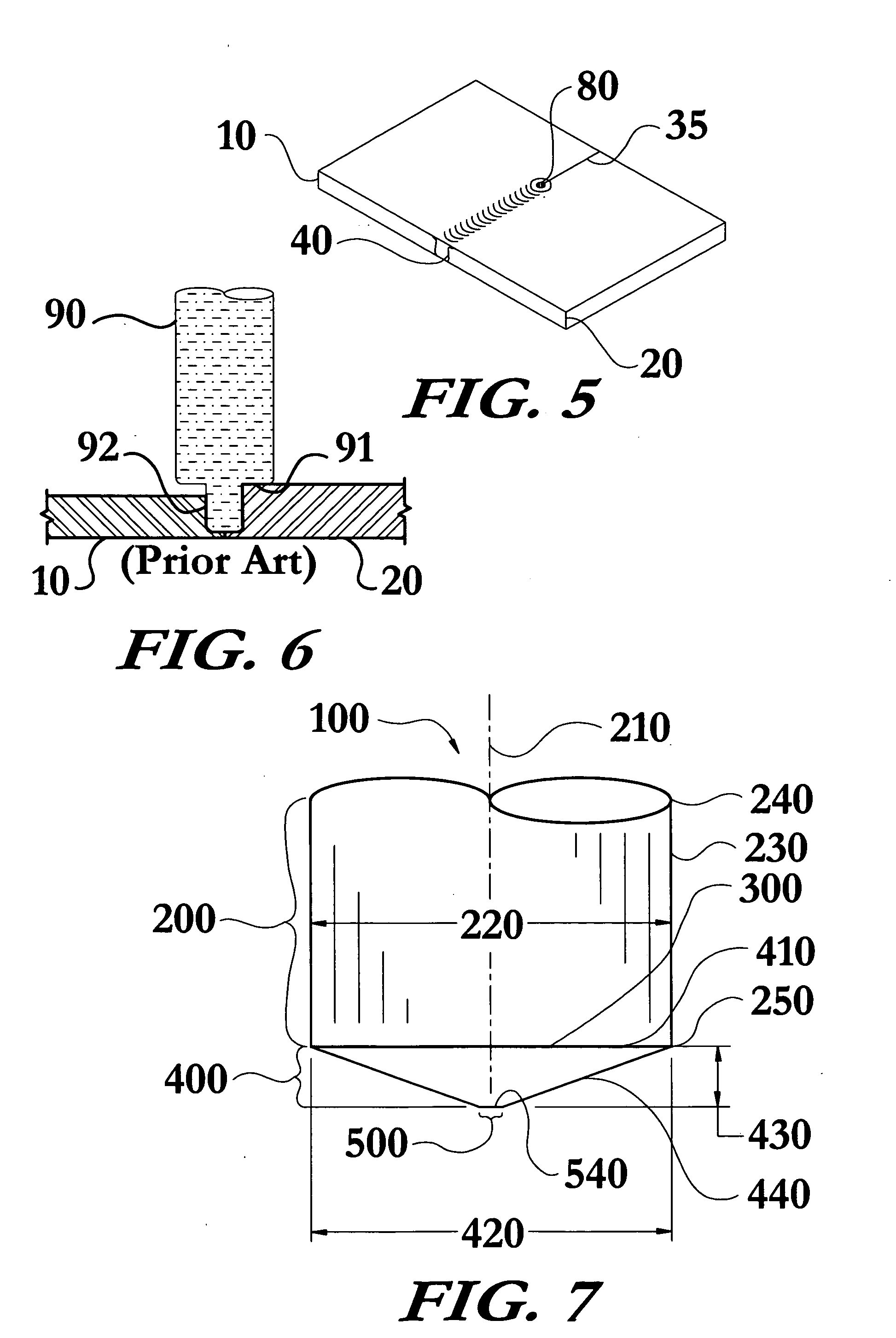
[0017] The head portion has a base with a diameter substantially equal to the diameter of the body portion, thereby forming a transition between the body portion and the head portion. The head portion includes a face that converges to the tip section. The transition from the body portion to the head portion is smooth in that it is uninterrupted by a shoulder or other projection. This lack of a shoulder has numerous advantages that have long been overlooked by those in the FSW industry. Prior methods and apparatus have indicated that top surface friction heating and weld material containment were essential to FSW.
[0018] The present invention's elimination of any portion of the tool that contacts the top surface of either workpiece away from the point at which the tool enters the workpiece(s) has several advantages. One such advantage is the elimination of the primary source of overheating. Additionally, another advantage of the present tool is the reduction of internal voids and lack of fusion that are associated with the transition region between the shoulder and the pin, as well as the transition from the pin to the pin tip. Further, the present design allows the use of a single tool in performing welds of varying depth and / or width, performing welds to join workpieces having differing thicknesses, performing welds to join workpieces having complex curvatures, and in retracting the tool to leave a weld free of an exit hole.

Problems solved by technology

Despite all the advantages of FSW, it has only found very limited commercial application to date due to many difficulties associated therewith.
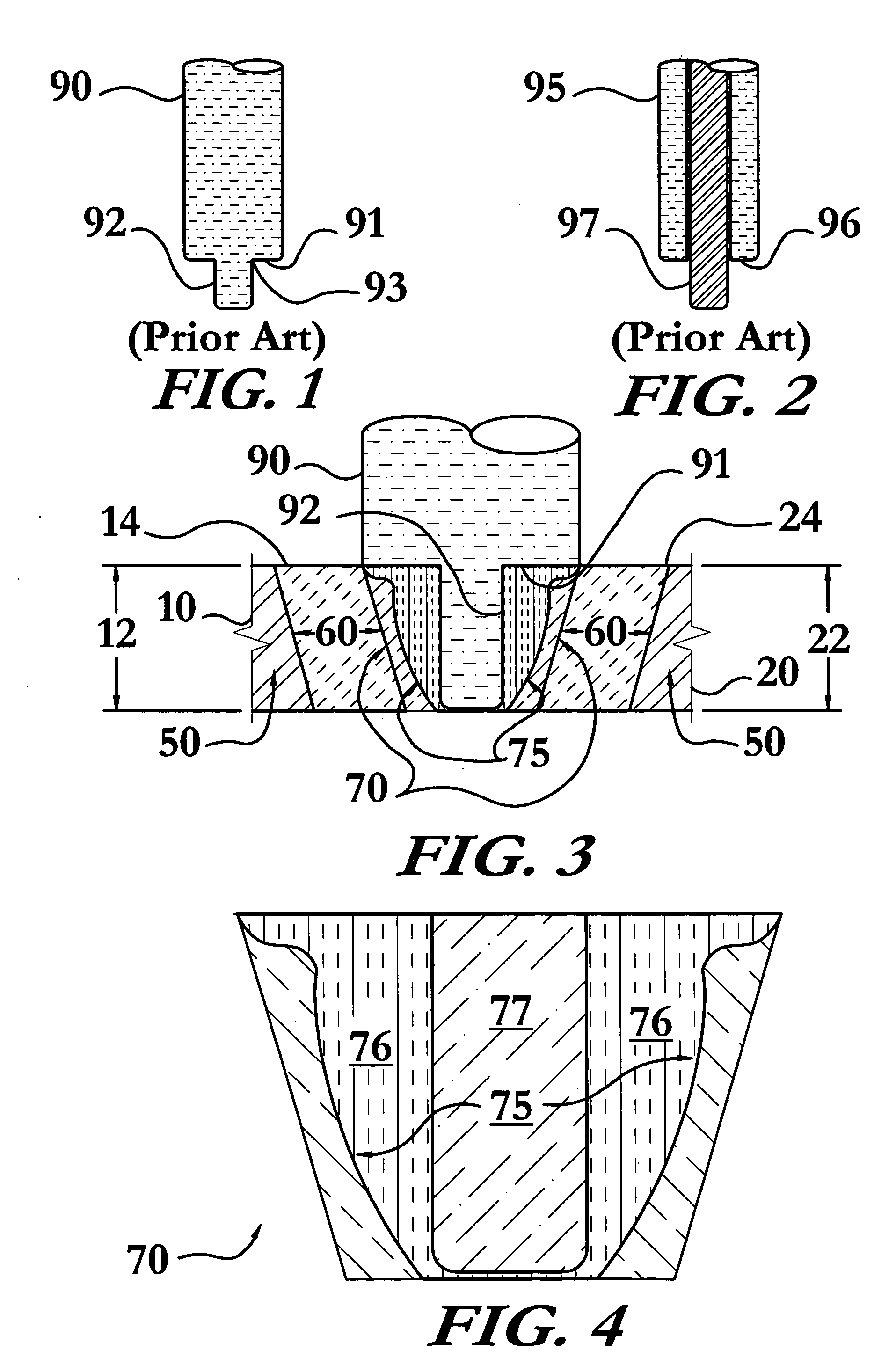
One early problem associated with single-piece FSW tools 90, as seen in FIG. 1, was that they leave an exit hole 80 in the weld 40, as seen in FIG. 5, that must be filled after completion of the friction stir weld.
Such single-piece FSW tools 90 are also plagued with premature breakage of the pin 92 during welding, resulting in the pin 92 being permanently lodged in the weld 40.
Another problem with both conventional shouldered FSW tools 90 and retractable pin tools 95 is the overheating caused by the shoulder 91, 96.
The retractable pin tool 95 may reduce the number of tools needed to make welds in materials having differing thicknesses, but it too is limited in that each retractable pin tool 95 has a limited useful range established by the diameter of the shoulder.
For instance, if the material is too thick or thin then under-heating or over-heating will occur.
Additionally, one can easily appreciate that the pin 97 of a retractable pin tool 95 designed for use in joining ⅛″ thick sheets will be ineffective and will fail if it is simply further extended from the shoulder 96 in trying to join ½″ thick plates.
Such lift-off and gouging results in welds having reduced aesthetic qualities that often require grinding of the surface and diminish the mechanical properties of the weld.
Such problems greatly limit the robustness of the conventional tools and methods, particularly on joints that vary in geometry or heat distribution due to part shape or tooling.
Additionally, the design of conventional shouldered FSW tools 90, 95 are prone to excessive wear and poor heat and load distribution.
These problems are largely attributable to the longstanding belief that FSW tools must have a relatively narrow pin and wide shoulder.

Method used


Image

  • Method of friction stir welding and retractable shoulderless variable penetration friction stir welding tool for same
  • Method of friction stir welding and retractable shoulderless variable penetration friction stir welding tool for same
  • Method of friction stir welding and retractable shoulderless variable penetration friction stir welding tool for same

Examples


Embodiment Construction

[0053] The non-consumable retractable shoulderless variable penetration friction stir welding tool and methods of friction stir welding of the present invention enable a significant advance in the state of the art. The preferred embodiments of the method and apparatus accomplish this by new and novel methods that are configured in unique and novel ways and which demonstrate previously unavailable but preferred and desirable capabilities. The description set forth below in connection with the drawings is intended merely as a description of the presently preferred embodiments of the invention, and is not intended to represent the only form in which the present invention may be constructed or utilized. The description sets forth the designs, functions, means, and methods of implementing the invention in connection with the illustrated embodiments. It is to be understood, however, that the same or equivalent functions and features may be accomplished by different embodiments that are al...


PUM

PropertyMeasurementUnit
opening angleaaaaaaaaaa
angleaaaaaaaaaa

Abstract

A method of friction stir welding and a non-consumable retractable shoulderless variable penetration friction stir welding tool. The tool includes a substantially cylindrical body portion, a head portion, and a tip section, each integral to the tool. The body portion has a longitudinal axis about which it is rotable, a diameter, a sidewall substantially parallel to the longitudinal axis, a proximal end, and a distal end. The head portion is located at the distal end of the body portion. The head portion has a base with a diameter substantially equal to the diameter of the body portion thereby forming a smooth transition between the body portion and the head portion, thus, the tool has no shoulder. The head portion includes a face that converges to the tip section. The tool is retractable, reduces overheating, improves weld quality by reducing internal voids and lack of fusion, and facilitates variable penetration welds.

Description

STATEMENT REGARDING FEDERALLY SPONSORED RESEARCH OR DEVELOPMENT [0001] This invention was not made as part of a federally sponsored research or development project. TECHNICAL FIELD [0002] The present invention relates to the field of friction stir welding; particularly, to a single piece non-consumable shoulderless friction stir welding tool and methods that can perform variable penetration welds, variable width welds, weld workpieces of differing thicknesses, weld workpieces having complex curvature, retract from the weld during welding without producing an exit hole, and improve the quality of friction stir welds. BACKGROUND OF THE INVENTION [0003] Those in the wide ranging materials joining industries have recognized the benefits of friction stir welding (FSW) since its invention, only to be precluded from widespread application due to a number of factors. FSW is a relatively simple method of solid phase welding developed by The Welding Institute in the early 1990's. The conventi...

Claims


Application Information

Patent Timeline
Patent Type & Authority Applications(United States)
IPC IPC(8): B23K20/12
CPCB23K20/1225B23K20/1255
Inventor TRAPP, TIMOTHY J.FISHER, JAMES J. JR.BERNATH, JEFFREY J.
Owner EDISON WELDING INSTITUTE INC
Why Eureka
Try Eureka