Anti-vibration bracket for tubular motor

a tubular motor and anti-vibration technology, applied in the direction of dynamo-electric machines, curtain suspension devices, building components, etc., can solve the problems of limiting the freedom of movement of the system and the majority of noise, and achieve the effect of reducing the propagation of vibrations and low horizontal stiffness

Inactive Publication Date: 2006-04-27
SOMFY SAS
View PDF11 Cites 80 Cited by
  • Summary
  • Abstract
  • Description
  • Claims
  • Application Information

AI Technical Summary

Benefits of technology

[0005] An electrical power-drive device includes a tubular motor assembly including a rotatable tube holding a motor therein. A motor bracket couples the tubular motor assembly to a fixture. The motor bracket includes a rigid member that can be fastened to the fixture, and plural flexible elements depending downwardly from the rigid me

Problems solved by technology

As further recognized herein, most of the noise is due to vibrations of the head rail and/or tube in which the tubular motor is disposed, caused by vibrations of the motor.
Furthermore, during attachment of the

Method used


Image

  • Anti-vibration bracket for tubular motor
  • Anti-vibration bracket for tubular motor
  • Anti-vibration bracket for tubular motor

Examples


first embodiment

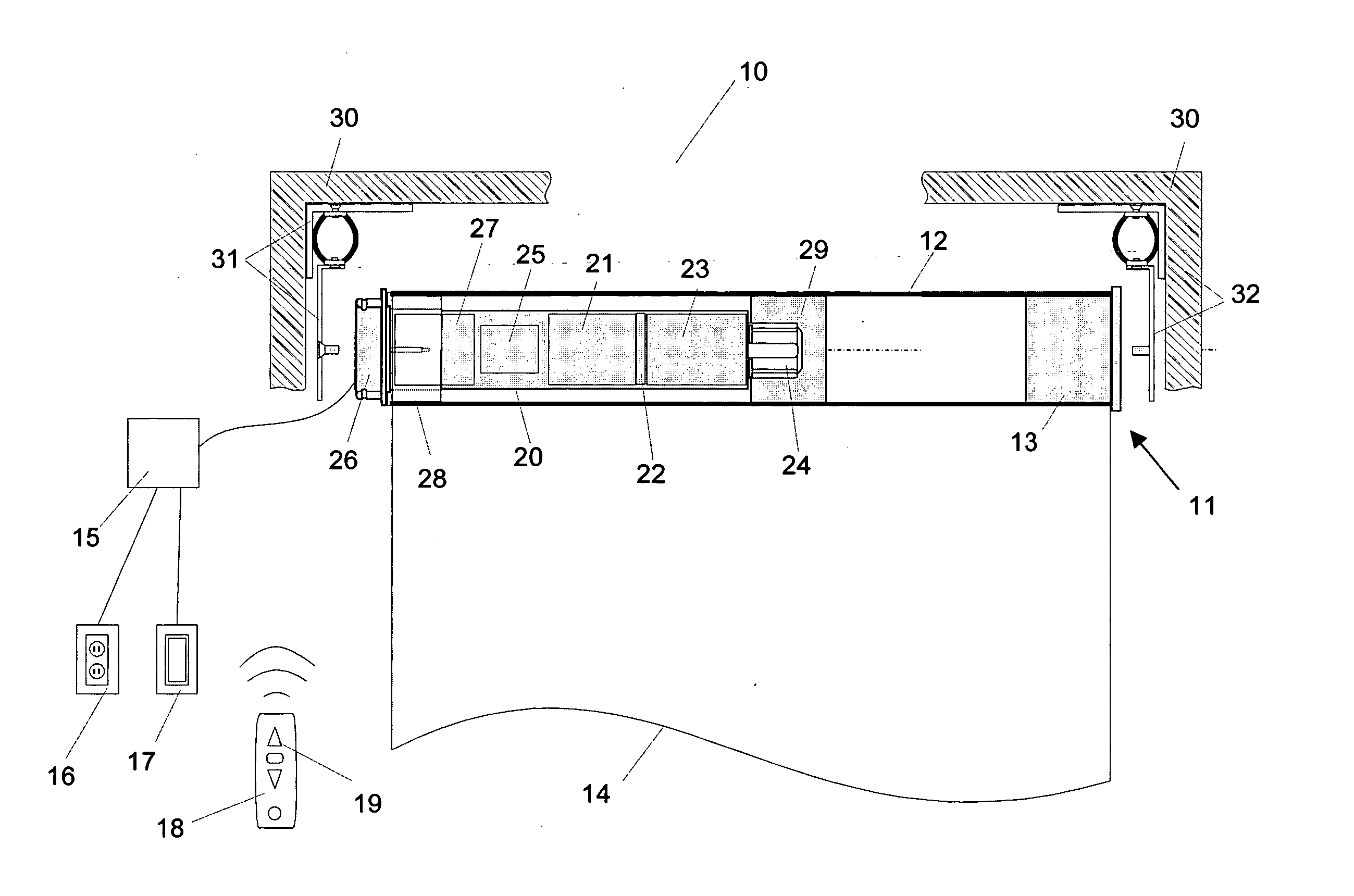
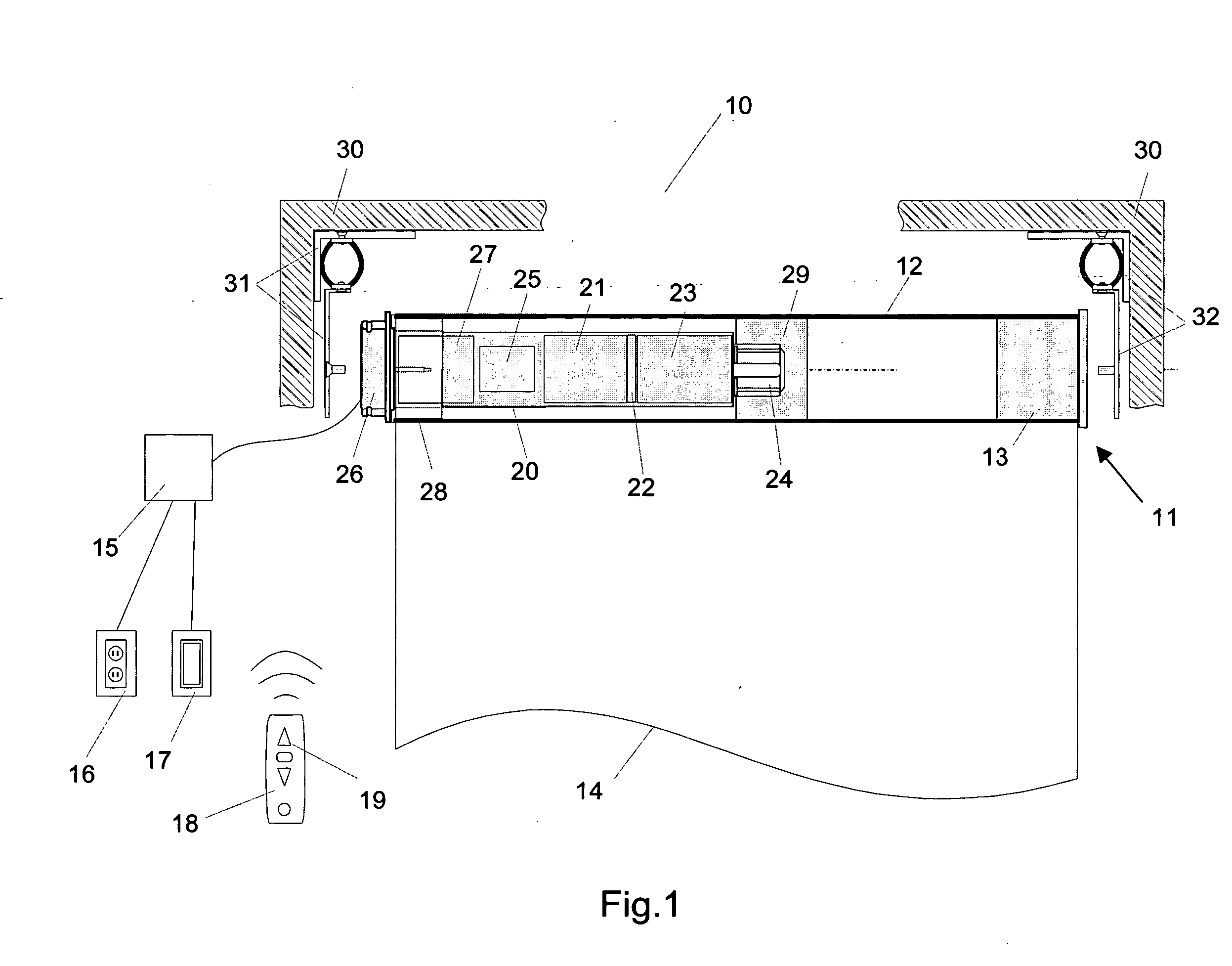
[0032] Now referring to a non-limiting illustrative embodiment in FIG. 2, one exemplary of the bracket 31 can be seen. In general, the present bracket may include three basic components, namely, a flexible component, implemented herein as plural flexible elements, that couples a rigid member to the motor assembly, with the rigid member being connected to a support surface, and a flexible mechanical engagement between the rigid member and flexible elements to prevent vibration and noise from being transmitted from the motor assembly to the support surface. While the motor bracket 31 is shown in FIG. 2, it is to be understood that the idler bracket 32 may be similarly constructed if desired.

[0033] The present invention critically recognizes that a significant increase of efficiency can be realized when the horizontal stiffness of the mounting system is lower and preferably much lower than the vertical stiffness. In this way, the present invention recognizes that the function of hangin...
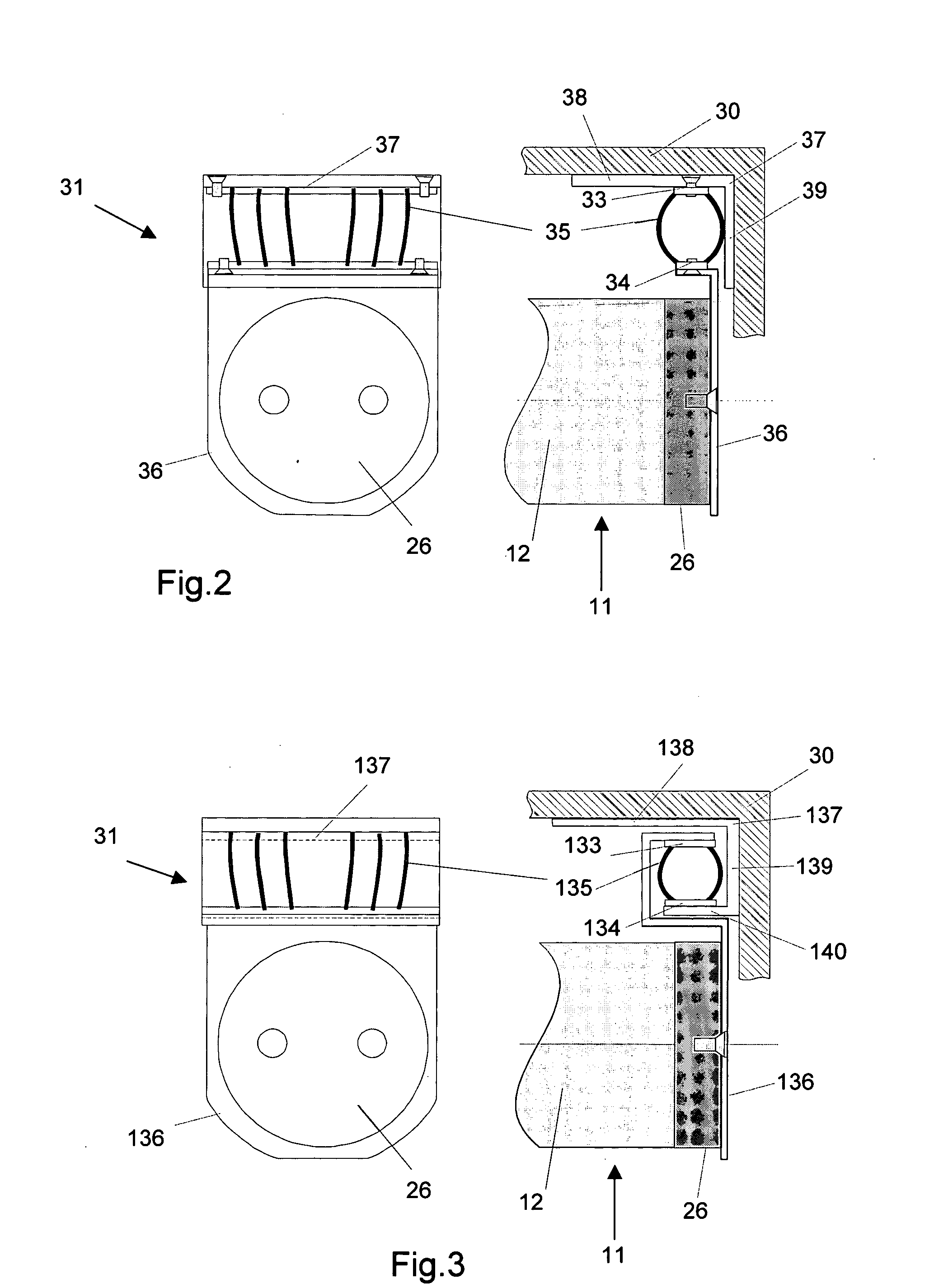
second embodiment

[0055]FIG. 6 shows an alternate bracket 60, which is a variant of the second embodiment, having a rigid member 62 defining a top surface 64. A metal movable suspension member 66 has bar-like or chain-like legs 68 connected to a second rigid member 65, which is connected to the head 26 of the actuator 20. This suspension member 66 includes a top piece 63 that is spaced above the top surface 64 of the rigid member 62. The top piece 63 may be parabolic as shown. Flexible elements in the form of coil or cylindrical springs 67 are disposed between the top piece 63 and the top surface 64 of the rigid member 62 as shown. The legs 68 may be rigid or flexible, and under no load only the center-most spring 67 need contact the top piece 63, or all springs 67 can be perpetually connected to both the top piece 63 and top surface 64. The arrows 69 represent the allowed tilt of suspended mass 11. If desired, the legs 68 may join the second rigid member 65 together under the head 26 of the actuator...


PUM


Abstract

A bracket includes a rigid member that can be fastened to a fixture such as a wall, and flexible elements depend downwardly from the rigid member and are engaged with a tubular motor assembly of a window covering, awning, projector screen, or the like, to couple the motor assembly to the fixture while attenuating the propagation of vibrations from the tubular motor assembly to the fixture. This reduces noise in the room. The flexible elements may be flexible strings, elastic strings, or coil springs and have horizontal stiffness coefficients much lower than the vertical stiffness coefficient.

Description

FIELD OF THE INVENTION [0001] The present invention relates generally to motorized window coverings. BACKGROUND OF THE INVENTION [0002] The present assignee has provided several systems for either lowering or raising a window covering, or for moving the slats of a window covering between open and closed positions, under control of a hand-held remote or other control device. These systems include a motor that is coupled through gears to the window covering activation mechanism. When the motor is energized in response to a user command signal, the activation mechanism moves the window covering. [0003] As recognized herein, it is desirable to minimize the noise emitted by such systems during operations. As further recognized herein, most of the noise is due to vibrations of the head rail and / or tube in which the tubular motor is disposed, caused by vibrations of the motor. The present invention understands that these vibrations are transmitted to the surface (such as a dwelling wall) s...

Claims


Application Information

Patent Timeline
IPC IPC(8): A47H1/10
CPCE06B9/174E06B9/72F16F1/428F16F15/04H02K5/24
Inventor HABEL, ALEXANDER K.NIEMIRKA, DANIEL B.CAVAREC, PIERRE-EMMANUELMORRISON, TIM
Owner SOMFY SAS
Why Eureka
Try Eureka