
Digital predistorter and predistortion method therefor

a digital and predistortion technology, applied in the direction of digital transmission, amplifier modification to reduce non-linear distortion, baseband system details, etc., can solve the problems of high distortion component, power generation a high level of distortion component, distortion component increase, etc., to achieve the effect of simplifying the adjustment of the vector adjuster of the predistorter

Inactive Publication Date: 2006-04-27
NTT DOCOMO INC
View PDF8 Cites 9 Cited by
  • Summary
  • Abstract
  • Description
  • Claims
  • Application Information

AI Technical Summary

Benefits of technology

[0029] the first vector adjuster adjusts the amplitude and phase so as to suppress a lower-than-(2k−1)th-order component in the output of the first adder.
[0033] a step of adjusting the amplitude and phase of the distortion component and adding the adjusted distortion component to the output signal of the linear transmission path, thereby predistorting the input signal,
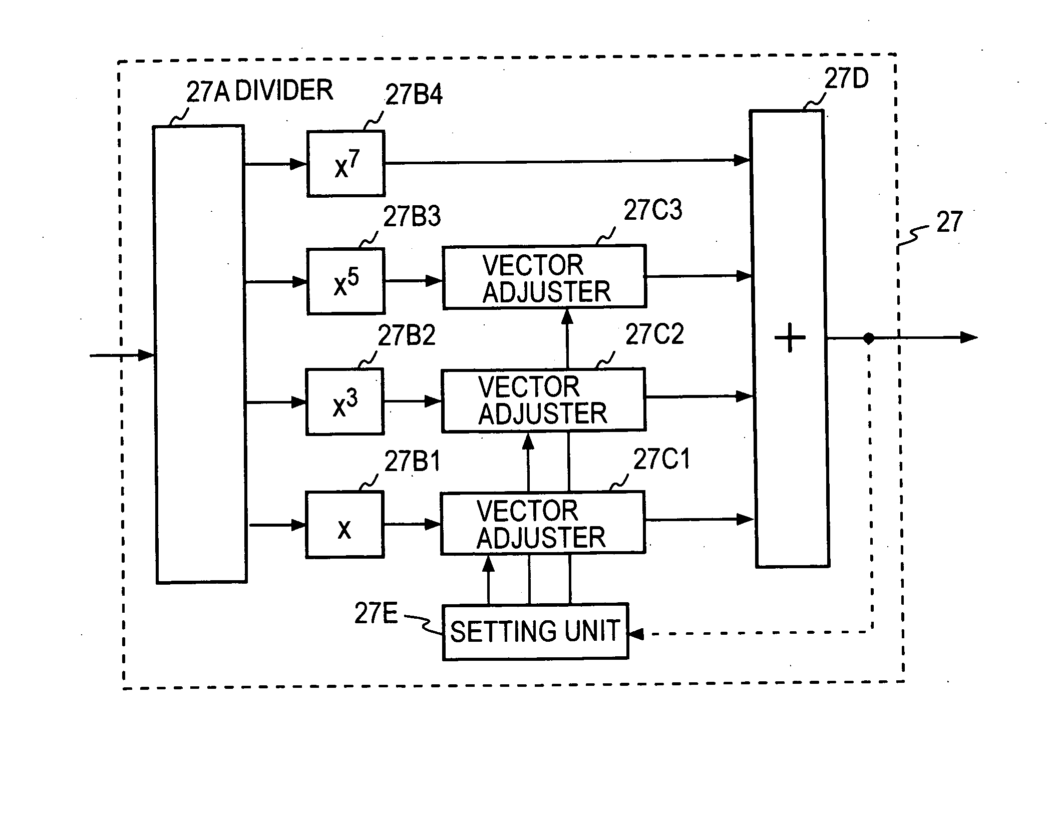
[0038] According to the present invention, since the lower-than-(2k−1)th-order components in the output of the (2k−1)th-order multiplier in the (2k−1)th-order distortion generator are suppressed, adjustments conducted by the vector adjusters of the predistorter are simplified.

Problems solved by technology

However, the power amplifier operating in the region close to the saturation power generates a high level of distortion component.
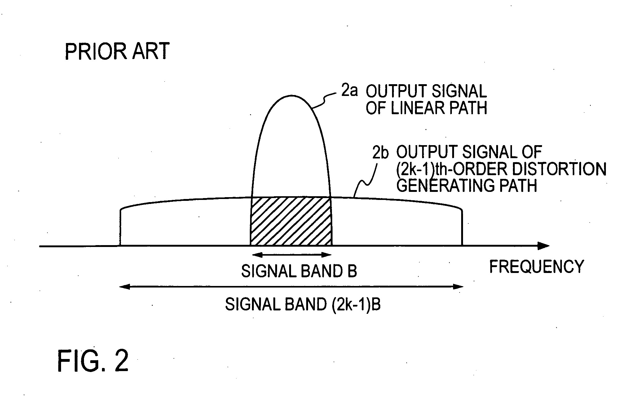
Thus, the output signal of the distortion generating path interferes with the output signal of the linear transmission path.
However, when the power amplifier operates in the region close to the saturation power to achieve high efficiency, the distortion component increases.
Therefore, the interference of the output signal of the distortion generating path with the output signal of the linear transmission path cannot be ignored.
However, such readjustment causes variation of the amplitude and phase of the transmission signal r(t), which causes variation of the amplitude and phase of the generated distortion component.
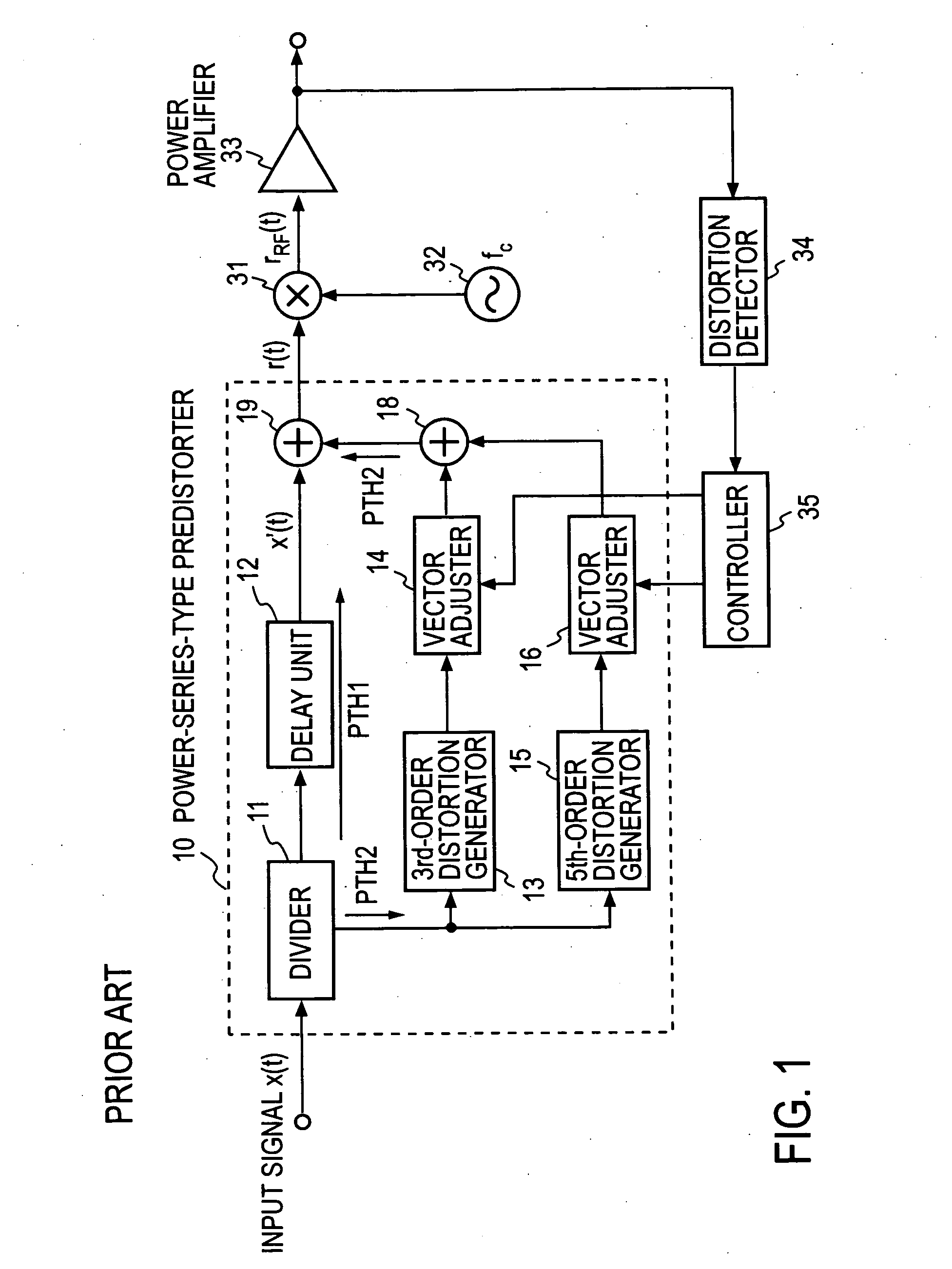
In this way, since the adjustment of the vector adjuster affects not only the output signal of the third-order distortion generating path but also the generated distortion component, adjustment of the vector adjuster becomes complicated.
Therefore, the output signal of the fifth-order distortion generating path interferes not only with the output signal of the linear transmission path but also with the output signal of the third-order distortion generating path.
As can be seen from the above description, the conventional predistorter has a problem that the output signal of the (2k−1)th-order distortion generating path has components that interfere with the output signal of the linear transmission path and the output signals of lower-than-(2k−1)th-order distortion generating paths.

Method used


Image

  • Digital predistorter and predistortion method therefor
  • Digital predistorter and predistortion method therefor
  • Digital predistorter and predistortion method therefor

Examples


first embodiment

[0061]FIG. 6 shows a predistorter according to a first embodiment of the present invention. A predistorter 20 according to the present invention is basically similar to the conventional predistorter shown in FIG. 1 in that it has a linear transmission path and one or more ith-order distortion generating paths. However, according to the principle of the present invention, the predistorter 20 differs from the conventional predistorter in the configuration of the ith-order distortion generator in each ith-order distortion generating path, as described below.

[0062] As shown in FIG. 6, the predistorter 20 according to the first embodiment comprises a divider 11 that divides an input signal and supplies the divided input signals to a linear transmission path PTH1 and a distortion generating path PTH2, a delay unit 12 disposed on the linear transmission path PTH1, a third-order distortion generator 23, a fifth-order distortion generator 25 and a seventh-order distortion generator 27 each ...

second embodiment

[0080]FIG. 10 shows a predistorter according to a second embodiment of the present invention. The predistorter according to the first embodiment described above and shown in FIG. 6 has a redundant configuration. The third-order distortion generator 23, the fifth-order distortion generator 25 and the seventh-order distortion generator 27 each have a third-order multiplier that carries out the same calculation. The fifth-order distortion generator 25 and the seventh-order distortion generator 27 each have a fifth-order multiplier that carries out the same calculation. However, according to the second embodiment, a vector adjuster and an adder are provided that vector-adjusts the output of each of the lower-than-ith-order multipliers and adds its output to the output of each ith-order multiplier (i=2k−1), that is, each of the (2j−1)th-order multipliers (k>j; j=1, 2, . . . ) are added to the output of the ith-order multiplier after adjusting the vector of the output of each of the (2j−1...


PUM


Abstract

A predistorter includes: a divider that divides an input signal and supplies the divided input signal to a linear transmission path and a distortion generating path; a (2k−1)th-order distortion generator that raises the signal supplied to the distortion generating path to the (2k−1)th power to generate a distortion component; a vector adjuster that adjusts the amplitude and phase of the output of the (2k−1)th-order distortion generator; and an adder that sums up the output of the vector adjuster and the output of the linear transmission path to generate a predistorted signal r(t), in which the (2k−1)th-order distortion generator comprises: a (2k−1)th-order multiplier (27B4) that raises the divided signal to the (2k−1)th power; a lower-than-(2k−1)th-order multiplier (27B3, 27B2, 27B1) that raises the divided signal to the 5th, 3rd and 1st power, respectively; a vector adjuster (27C3, 27C2, 27C1) that adjusts the amplitude and phase of the output of the lower-than-(2k−1)th-order multiplier; and an adder (27D) that sums up the output of the vector adjuster and the output of the (2k−1)th-order multiplier.

Description

BACKGROUND OF THE INVENTION [0001] 1. Field of the Invention [0002] The present invention relates to a predistorter for linearizing a power amplifier for a radio communication transmitter and a predistortion method therefor. [0003] 2. Description of the Related Art [0004] Microwave power amplifiers used in base stations or terminals of cellular phone systems require high power efficiency for achieving lower power consumption and compactness. In general, the efficiency of a power amplifier increases as its operating point approaches the saturation output power, and thus, it is desirable that the power amplifier operates in a region close to the saturation output power. However, the power amplifier operating in the region close to the saturation power generates a high level of distortion component. In a base station or a terminal, the power amplifier has to achieve a predetermined attenuation level of a distortion component outside the transmitted signal bandwidth (a predetermined adj...

Claims


Application Information

Patent Timeline
IPC IPC(8): H04L25/49
CPCH03F1/3241H03F1/3247H03F1/3282H04B1/0475H04B2001/0425H03F1/32H03F1/26H03F3/45
Inventor MIZUTA, SHINJISUZUKI, YASUNORINARAHASHI, SHOICHI
Owner NTT DOCOMO INC
Learn More