Image forming apparatus

Inactive Publication Date: 2006-04-27
CANON KK
View PDF3 Cites 10 Cited by
  • Summary
  • Abstract
  • Description
  • Claims
  • Application Information

AI Technical Summary

Benefits of technology

[0011] The employment of the above described structural arrangement makes it possible to localize the heating of an image forming apparatus by a heating means, to the portion of the image bearing member, which is facing a charging means, and the portions of the image bearing member adjacent to this portion. Therefore, it is possible to provi

Problems solved by technology

That is, as an image forming operation is continued, the image forming apparatus gradually reduces in image quality in that it begins to yield images suffering from a defect called a slur, that is, a spot that appears blurred or unclear like a picture of “flowing water”.
Thus, their adhesion to the peripheral surface of the photosensitive member increases the amount of moisture on the peripheral surface of the photosensitive member, which in turn causes the paper dust from recording paper (object across which recording is made), toner,

Method used


Image

  • Image forming apparatus
  • Image forming apparatus
  • Image forming apparatus

Examples


embodiment 1

(1) Example of Image Forming Apparatus

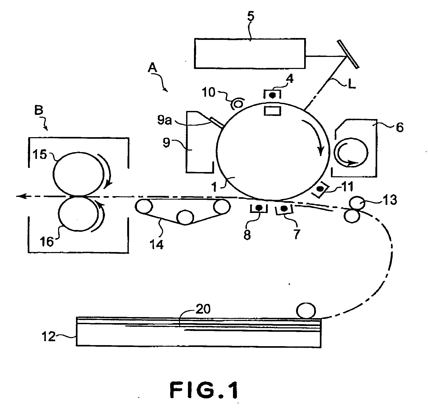
[0024]FIG. 1 is a schematic drawing of a typical image forming apparatus to which the present invention is very effectively applicable. This image forming apparatus (copying machine, printer, etc.) is such an image forming apparatus that employs, as its image formation process, one of the electrophotographic processes of the transfer type which includes one of the exposing methods which expose an image bearing member by scanning the image bearing member with the use of a beam of laser light.

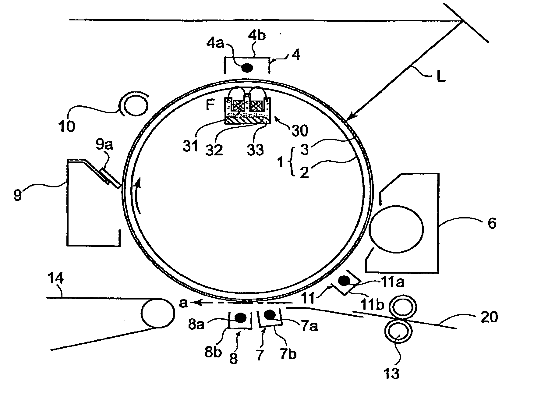
[0025] Referring to FIG. 1, designated by a referential symbol A is the image forming portion of the image forming apparatus, which comprises an electrophotographic photosensitive member 1 (which hereinafter may be referred to simply as photosensitive member) as an image bearing member, which is in the form of a rotatable cylindrical drum. Disposed in the adjacencies of the peripheral surface of this photosensitive member 1 are a primary charging device 4,...

embodiment 2

[0047] In this embodiment, a temperature detecting means is disposed between a photosensitive member and a magnetic field generating means. The means, members, etc., of the image forming apparatus in this embodiment, which are identical to those in the first embodiment, are given the same referential symbols as those given to describe the first embodiment, and will be not be described here to avoid the repetition of the same descriptions.

[0048]FIG. 7 is a schematic drawing of the photosensitive member heating means in this embodiment, which is similar to that in the first embodiment, except that the one in this embodiment is provided with a temperature detecting means 40, which is disposed between the photosensitive member and magnetic field generating means. In this embodiment, the temperature detecting means 40 is attached to the holder 33 of the magnetic field generating member 30 with the interposition of a supporting member 41, which is an elastic member for ensuring that the ...

embodiment 3

[0053] In this embodiment, the primary charging device 4 is disposed a predetermined angle deviated in the rotational direction of the photosensitive member 1 relative to the vertical line which coincides with the rotational axis of the photosensitive member 1. The means, members, etc., of the image forming apparatus in this embodiment, which are identical to those in the first embodiment, are given the same referential symbols as those given to describe the first embodiment, and will be not be described here to avoid the repetition of the same descriptions.

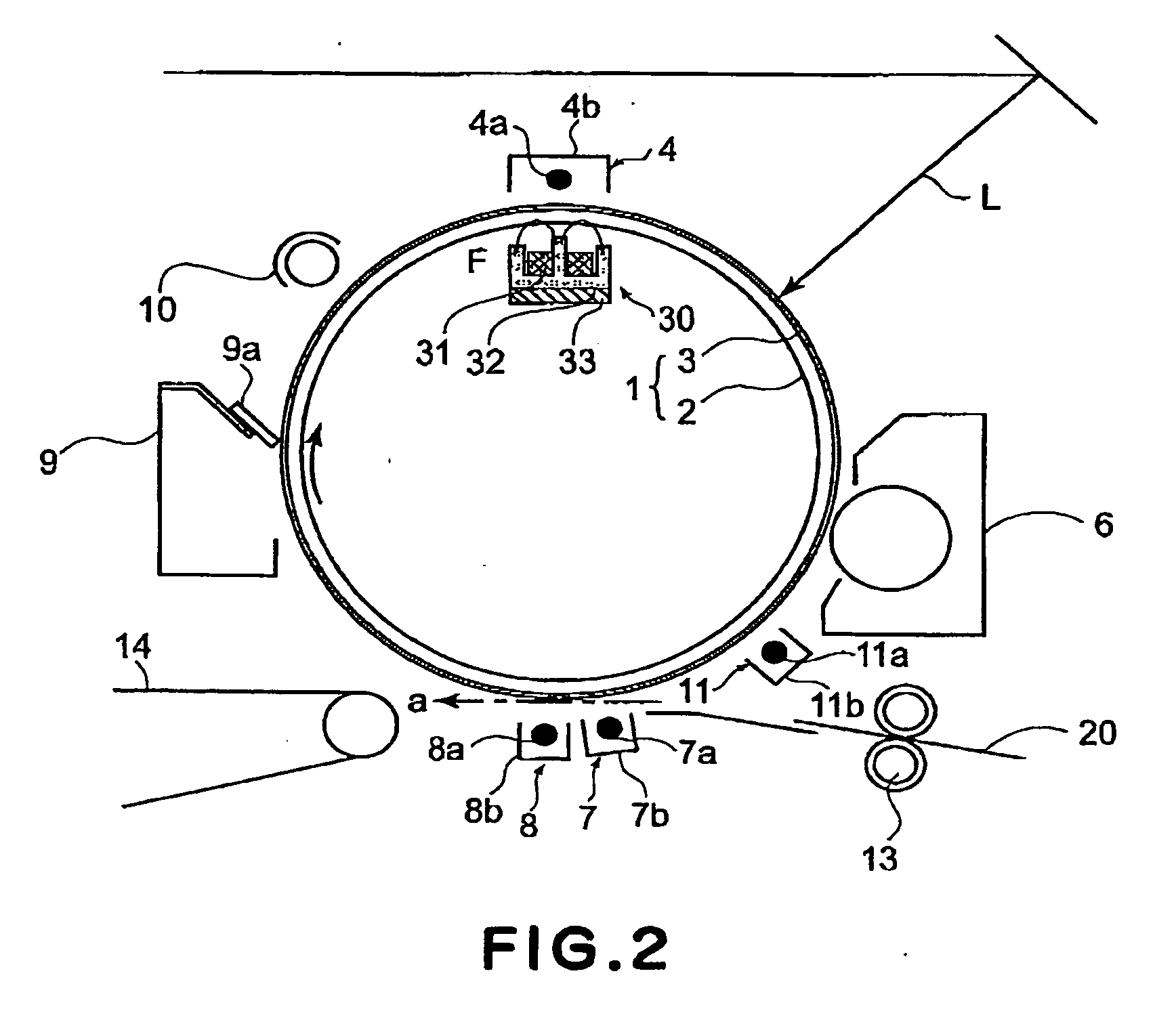
[0054]FIG. 8 is a schematic drawing of the photosensitive member heating means in this embodiment, showing the positional relationship of the magnetic field generating member 30 relative to the charging device (primary charging device in FIG. 8). The structure of the image forming portion A in this embodiment is the same as that in the first embodiment described with reference to FIG. 2, except that in the case of the image form...


PUM


Abstract

An image forming apparatus includes an image bearing member; image forming means for forming an image on said image bearing member through steps including a step of electrically charging said image bearing member to a substantially uniform potential, wherein said image bearing member is repeatedly usable for forming images; and heating means, disposed adjacent to said image bearing member, for locally heating said image bearing member.

Description

FIELD OF THE INVENTION AND RELATED ART [0001] The present invention relates to an image forming apparatus such as a copying machine, a printer, or the like, which employs a single or multiple image bearing members such as an electrophotographic photosensitive member, an electrostatically writable dielectric member, the likes and forms images with the use of one of such image formation processes as the electrophotographic and electrostatic recording processes, which include the step of uniformly charging the image bearing member, while repeatedly using the image bearing member. [0002] More specifically, the present invention relates to an image forming apparatus which is substantially smaller in the effects of the byproducts of the electrical discharge which repeatedly occurs between the image bearing member(s) and charging means of the image forming apparatus, is lower in energy consumption, and is more reliable than an image forming apparatus in accordance with the prior art When f...

Claims


Application Information

Patent Timeline
IPC IPC(8): G03G15/00G03G15/02
CPCG03G15/0258G03G21/20G03G2215/027
Inventor SUZUKI, HITOSHI
Owner CANON KK
Why Eureka
Try Eureka