Method and device for cooperation-removal of PM2,5 in flue gas wet desulphurization

A PM2.5, wet desulfurization technology, applied in separation methods, chemical instruments and methods, dispersed particle separation, etc., can solve the problem of low capture efficiency of PM2.5

Inactive Publication Date: 2008-07-16
SOUTHEAST UNIV
View PDF0 Cites 49 Cited by
  • Summary
  • Abstract
  • Description
  • Claims
  • Application Information

AI Technical Summary

Problems solved by technology

Therefore, although the existing flue gas wet desulfurization technology can effectively remove SO 2 and coarse dust, but for PM 2.5 The capture efficiency is very low, resulting in a large amount of PM 2.5 into the atmosphere

Method used


Image

  • Method and device for cooperation-removal of PM2,5 in flue gas wet desulphurization
  • Method and device for cooperation-removal of PM2,5 in flue gas wet desulphurization

Examples


Embodiment 1

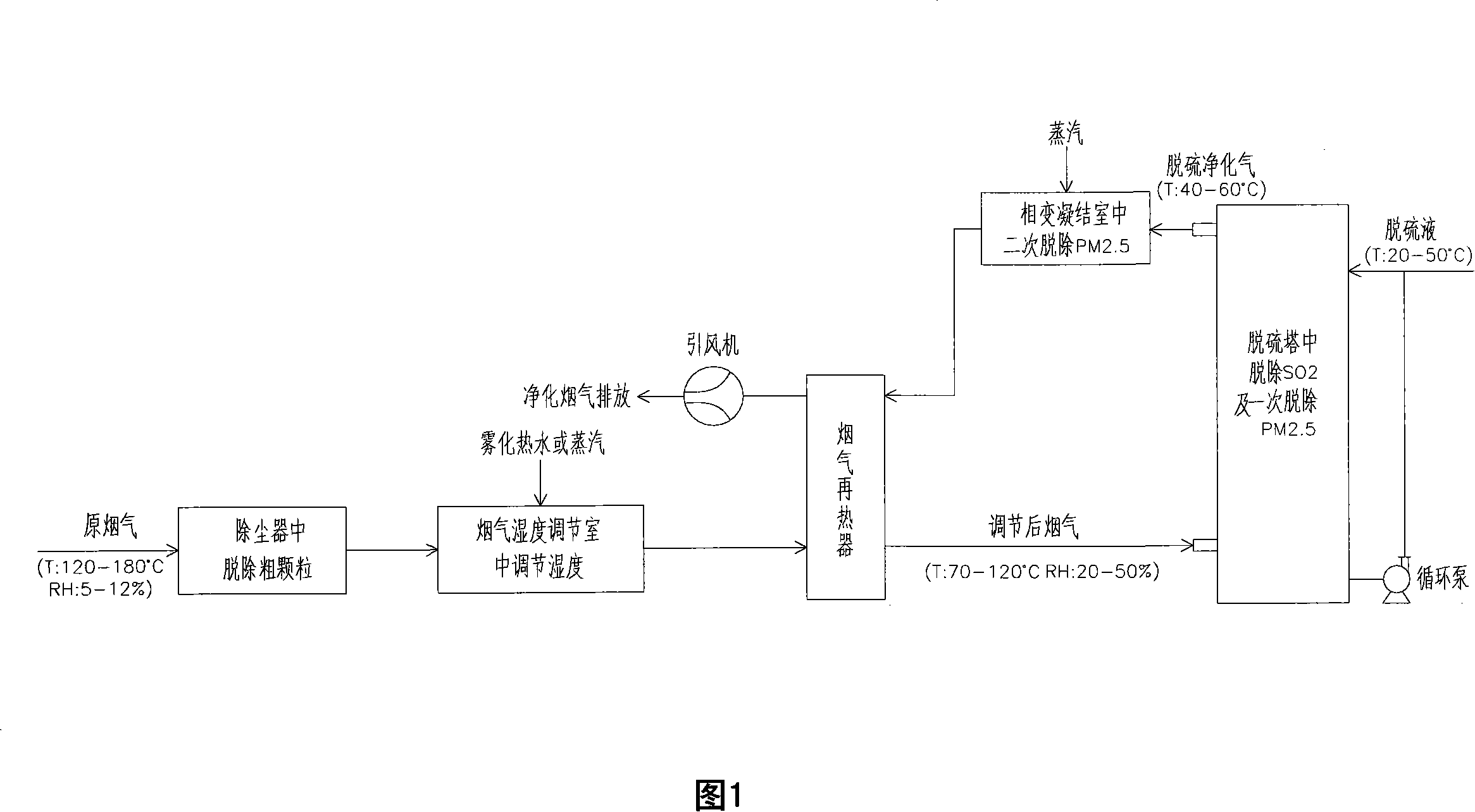
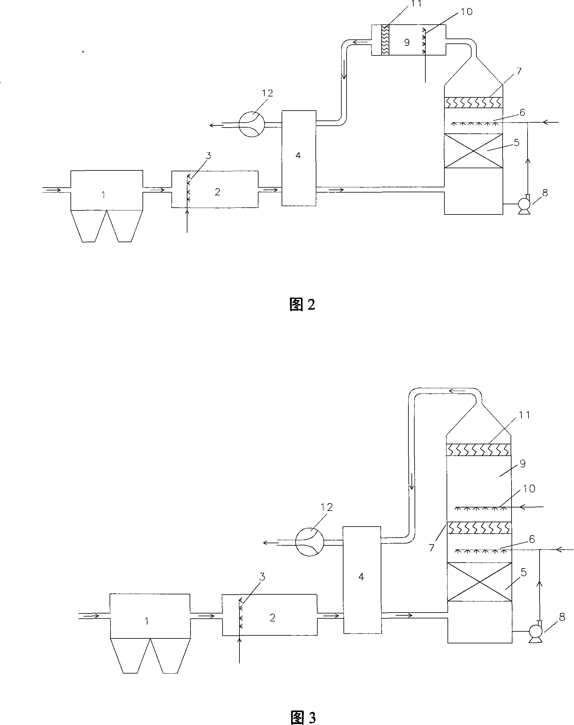
[0019] Synergistic removal of PM in flue gas wet desulfurization of the present invention 2.5 The method is shown in Figure 1: The dust-containing flue gas produced by the coal-fired boiler is removed by the dust collector (such as electrostatic precipitator) 1 after removing coarse particles with a particle size of ≥2.5 μm, and then enters the flue gas humidity control room 2 and is atomized The water nozzle 3 sprays atomized water droplets with a particle size of 20-30μm, and uses the heat of the flue gas to completely evaporate the atomized water droplets in the humidity control room 2. The amount of atomized water added is based on the flue gas's adjusted relative humidity from 5 to 12 % Increased to 20-50% to confirm. The flue gas with humidity adjustment enters the desulfurization tower 5 from the lower part of the desulfurization tower. In the desulfurization tower 5, the high-temperature wet flue gas (temperature: 70~120℃) is in countercurrent contact with the medium and l...

Embodiment 2

[0022] As shown in Figure 3, the difference from Example 1 is that the phase change condensation chamber is not specially set, but the height of the desulfurization tower is appropriately increased, and the head space of the desulfurization tower 5 (that is, the position above the demister 7 of the desulfurization tower) is used for phase change. Condensing chamber 9 is injected with an appropriate amount of steam. A high-efficiency demister 11 is installed on the top of the tower. The purified flue gas at the outlet of the tower is heated by the flue gas reheater 4 and then discharged from the chimney.

Embodiment 3

[0024] A steam nozzle is installed in the flue gas humidity control chamber 2 to directly inject an appropriate amount of steam to adjust the flue gas moisture content, and the rest is the same as in Embodiment 1 or 2.


PUM


Abstract

The invention provides a method that fully utilizes the characteristics of relatively high humidity content of flue gas in the existing wet desulfurization technology and employs vapor phase change theory to effectively remove SO2 through WFGD so as to cause PM2.5 to be condensed and enlarged as well as be removed effectively and a device thereof. The invention has simple technique, and arranging a moisture regulation chamber for the flue gas and a phase change condensing chamber in the existing flue gas wet desulfurization devices can cause the wet desulfurization device to have the effect of enlarging and removing PM2.5 granules. The invention is widely used in the existing wet desulfurization devices for the flue gas generated by power plants.

Description

1. Technical Field [0001] The invention belongs to PM in flue gas 2.5 Particulate removal technology, especially related to the application of steam phase change principle in flue gas wet desulfurization to remove PM together 2.5 The method and its device. 2. Background technology [0002] Inhalable particulate matter is currently the primary pollutant of the urban atmospheric environment in my country, especially PM with an aerodynamic diameter less than 2.5μm 2.5 The pollution problem is very serious, mainly due to PM 2.5 The specific surface area of ​​particles is large, and it is easy to accumulate various heavy metals and chemical carcinogens, while conventional dust removal technology is difficult to effectively capture them. For example, wet desulfurization towers (including mist eliminators, scrubbers) can affect PM 2.5 The trapping efficiency is very low, but the removal efficiency of particles above 3~5μm can reach more than 70~90%; Wang Hui of Tsinghua University and o...

Claims


Application Information

Patent Timeline
Patent Type & Authority Applications(China)
IPC IPC(8): B01D53/78
Inventor 杨林军颜金培沈湘林
Owner SOUTHEAST UNIV
Why Eureka
Try Eureka