
Battery case for an electric bicycle and a mounting structure thereof

a technology for electric bicycles and mounting structures, which is applied in the direction of rider propulsion, cycle equipment, cell components, etc., can solve the problems of spoiled bicycle appearance, increased cost, and inability of riders to read the indications on the battery case when the electric bicycle is running, so as to save meter costs and simplify circuit installation.

Inactive Publication Date: 2006-04-27
WU YI CHIEH
View PDF7 Cites 25 Cited by
  • Summary
  • Abstract
  • Description
  • Claims
  • Application Information

AI Technical Summary

Benefits of technology

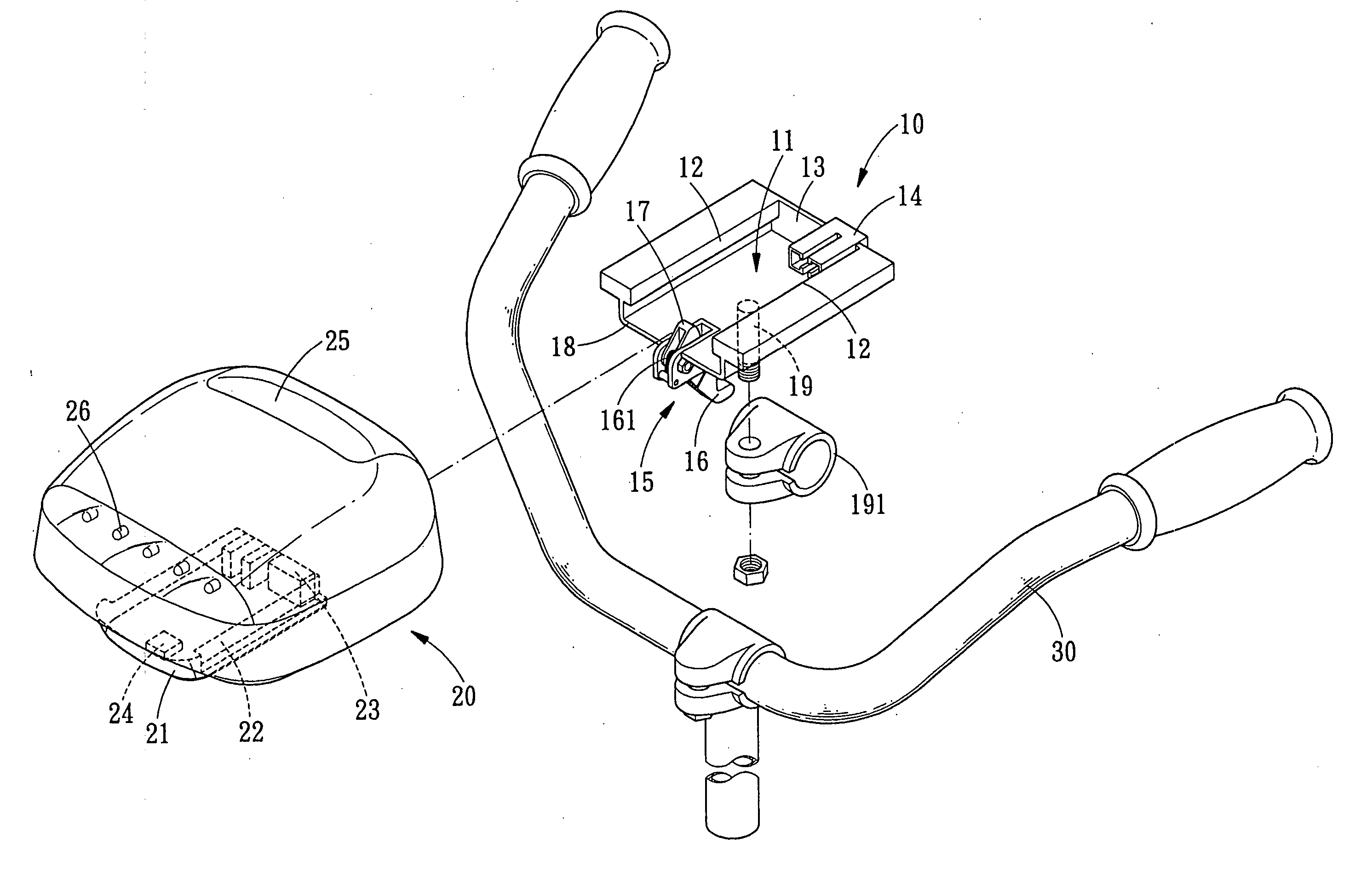
[0008] The primary objective of the present invention is to provide a battery case for an electric bicycle and the mounting structure thereof. The battery case is disposed at the handlebar of an electric bicycle right within the rider's line of sight. If the battery case is provided with battery indicator, speed indicator, operation light, headlight and the like instruments, then the user rider can read it clearly, and the battery case also can be used as a meter. Thus, not only the meter cost is saved, but also the circuit installation is relatively simplified.
[0009] The secondary objective of the present invention is to provide a battery case for an electric bicycle and the mounting structure thereof. The weight of the battery case is transmitted to the flanges of the mounting base through the groove, and the connection between the battery case and the mounting base is strengthened by locking the projection of the locking assembly into the locking cavity. Therefore, the battery case not only can be easily assembled and disassembled but also can be positioned firmly.

Problems solved by technology

However, the battery case is normally provided with battery indicator, operation light and the like functions, so the rider is unable to read the indications on the battery case when the electric bicycle is running.
However, adding a control panel not only increases the cost, but also needs a circuit to be connected between the battery case and the control panel.
Therefore, not only the appearance of the bicycle is spoiled, but also the circuit will cause extra problems.

Method used


Image

  • Battery case for an electric bicycle and a mounting structure thereof
  • Battery case for an electric bicycle and a mounting structure thereof
  • Battery case for an electric bicycle and a mounting structure thereof

Examples


Embodiment Construction

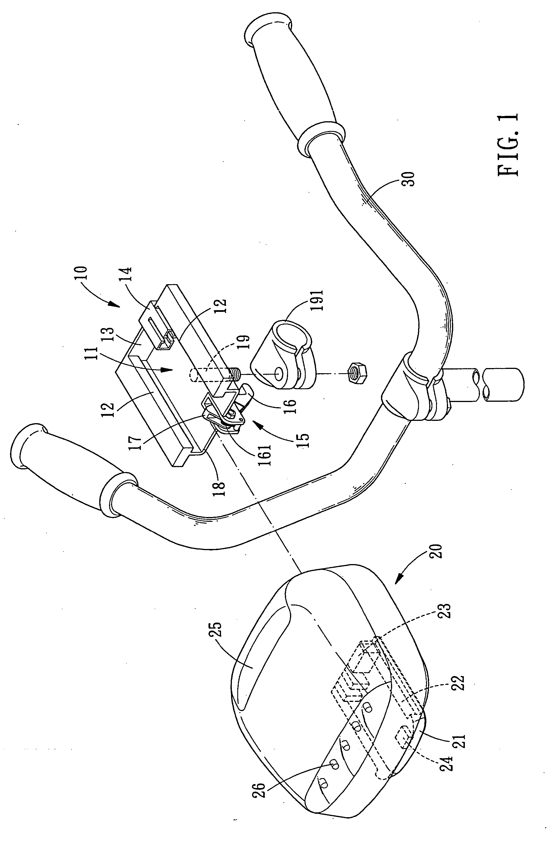
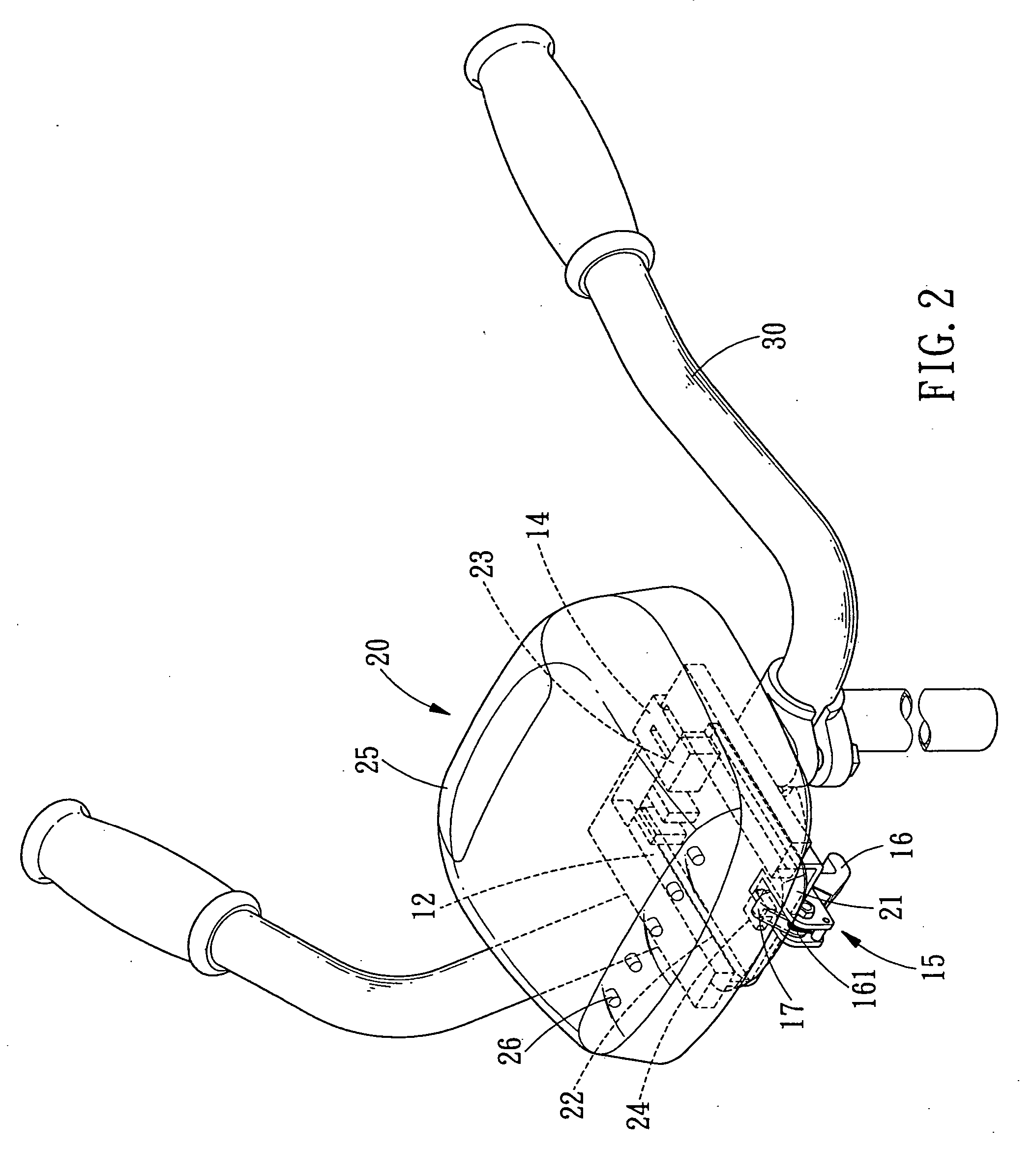
[0019] Referring to FIGS. 1-3, a battery case for an electric bicycle and a mounting structure thereof is shown and comprises a mounting base 10 and a battery case 20 mounted on a handlebar 30 of an electric bicycle.

[0020] The mounting base 10 is provided with a recess 11 having two flanges 12 located opposite each other. A terminal 14 is disposed at the rear sidewall 13 of the mounting base 10 and located between the two flanges 12. At the front gap of the recess 11 is a locking assembly 15 which can rotate a projection 17 by rotating a follower 16, so that the projection 17 will be enabled to move out of and back into the bottom surface 18 of the recess 11 according to needs. The follower 16 of the locking assembly 15 will return to its original position automatically through a spring 161. The mounting base 10 is fixed to the handlebar 30 of the electric bicycle through a clamp 191 and a bolt 19 extending from the bottom surface 18.

[0021] The battery case 20 is provided at its b...


PUM


Abstract

A battery case for an electric bicycle and a mounting structure thereof is disposed at the handlebar of an electric bicycle. If the battery case is provided with battery indicator, speed indicator, headlight and the like instruments, the user rider can read it easily, and the battery case also can be used as a meter. Thus, not only the meter cost is saved, but also the circuit installation is simplified. Furthermore, the battery case is loaded on the flanges of the mounting base, and the connection between the battery case and the mounting base is strengthened by a projection and a locking cavity. Therefore, the battery case not only can be easily assembled and disassembled but also can be positioned firmly.

Description

BACKGROUND OF THE INVENTION [0001] 1. Field of the Invention [0002] The present invention relates to a battery case for an electric bicycle and a mounting structure thereof, and more particularly to a design capable of enabling the battery case to be assembled to the handlebar of an electric bicycle easily and firmly. [0003] 2. Description of the Prior Arts [0004] Along with the development of technology in battery industry, the battery, such as nicad battery, Ni-MH Battery, Li-ion battery and so on, is minimized substantially both in weight and size. Since it is rechargeable, the battery can be applied in the electronic products or the electronic bicycle. [0005] The battery case for an electric bicycle is normally disposed on the frame beneath the rear seat, or on the saddle pillar. However, the battery case is normally provided with battery indicator, operation light and the like functions, so the rider is unable to read the indications on the battery case when the electric bicycl...

Claims


Application Information

Patent Timeline
IPC IPC(8): H01M2/10H01M10/50B60L50/15B62J9/00B62J11/00B62J99/00B62K19/30B62M6/40B62M6/80B62M6/90H01M10/60H01M10/613H01M10/625H01M10/6556H01M10/6563
CPCB60L11/1801B60L11/1874B60L2200/12B62J11/00Y02T10/705B62M6/40B62M6/90Y02T10/7005B62K19/30B60L50/53B60L58/26Y02T10/70Y02E60/10H01M50/20H01M50/204H01M50/375
Inventor WU, YI-CHIEH
Owner WU YI CHIEH
Learn More