Wireless terminal location using apparatus and methods employing carrier diversity

a wireless terminal and antenna technology, applied in the direction of site diversity, transmission monitoring, receiver monitoring, etc., can solve the problems of increasing weight and size, increasing cost, and consuming limited battery power resources during operation

Active Publication Date: 2006-04-27
QUALCOMM INC
View PDF6 Cites 76 Cited by
  • Summary
  • Abstract
  • Description
  • Claims
  • Application Information

AI Technical Summary

Benefits of technology

[0020] One exemplary wireless communications device, e.g., a wireless terminal such as a mobile node, implemented in accordance with the present invention, determines its geographic location based upon received signals from three or more base stations using at least two different carrier frequencies. The exemplary wireless communications device comprises, in some but not necessarily all embodiments, a receiver for receiving first, second, and third signals from first, second, and third base stations, respectively, said first and second signals corresponding to first and second carrier frequencies, said first and second carrier frequencies being different. The exemplary wireless terminal may also include a power measurement module for measuring the received power of said first, second and third signals and a relative transmission power determination module for determining relative transmission powers between said first, second, and third signals. The exemplary wireless terminal may further comprise a channel gain ratio module for determining at least two channel gain ratios, said at least two channel gain ratios including a first channel gain ratio and a second channel gain ratio, the first channel gain ratio being a channel gain ratio between a first channel gain and a second channel gain, said first channel gain being a channel gain between said first base station and said wireless communications device, said second channel gain being a channel gain between said second base and said wireless communications device, and a third channel gain being a channel gain between said third base station and said wireless communications device. The exemplary wireless communications device further comprises a geographic area determination module for determining a geographic area corresponding to said at least two determined channel gain ratios.

Problems solved by technology

This requires additional specialized circuitry and a specialized antenna, adding cost, increasing weight and size, and consuming the limited battery power resources during operation.
In addition, GPS reception, may be unavailable in many locations, e.g., where a line of signal cannot be obtained from the GPS antenna to a set of satellites, e.g., 3 or more satellites, to obtain a solution.

Method used


Image

  • Wireless terminal location using apparatus and methods employing carrier diversity
  • Wireless terminal location using apparatus and methods employing carrier diversity
  • Wireless terminal location using apparatus and methods employing carrier diversity

Examples


Embodiment Construction

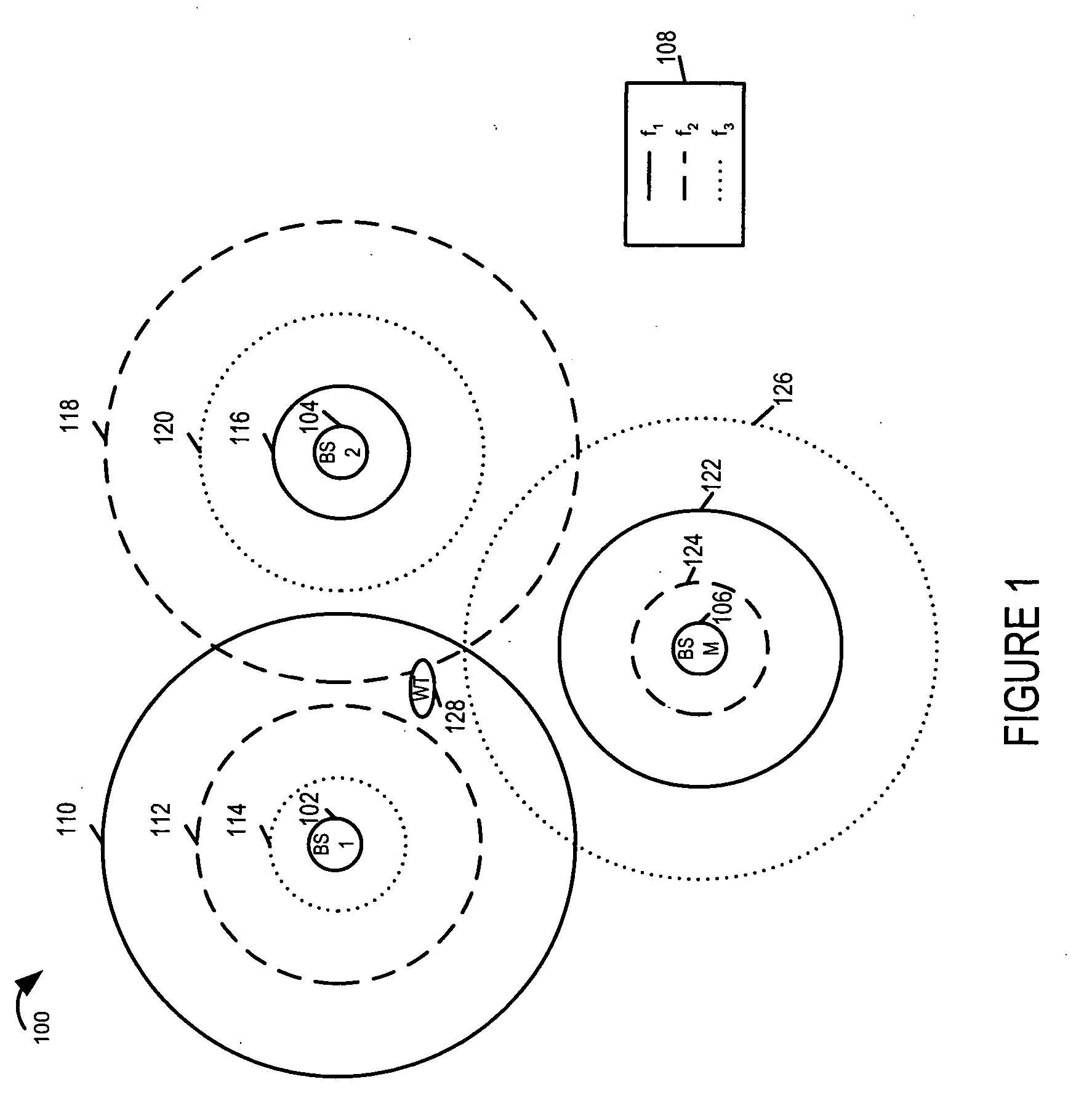
[0022]FIG. 1 is a drawing showing three exemplary base stations, BS 1102, BS 2104, BS M 106 in a wireless communications system 100 using carrier diversity. Each BS 102, 104, 106, transmits using a plurality, e.g., three different carrier frequencies, each at a different power level. The power transmission levels for a given carrier for adjacent base stations are different. The power level strength for a given carrier and base station is indicated by the relative size of the corresponding circle around the base station. As shown in legend 108, the solid line is used to represent the f1 carrier frequency; the dashed line is used to represent the f2 carrier frequency; the dotted line is used to represent the f3 carrier frequency. BS1102 transmits using carrier frequencies (f1, f2, f3) at (high, medium, low) power level represented by circles (110, 112, 114), respectively. BS2104 transmits using carrier frequencies (f1, f2, f3) at (low, high, medium) power level represented by circles ...


PUM


Abstract

Wireless terminals, e.g., mobile nodes, receive, identify, and measure broadcast signals from a plurality of cells. They determine relative transmission power relationships corresponding to the received measured signals and determine at least two channel gain ratios. A geographic area is determined corresponding to the obtained at least two channel gain ratios and information indicating the geographic region in which such gain ratios may be detected. Each cell's base station transmits broadcast signals, e.g., beacon signals, pilot signals, and/or assignment signals for one more carriers. Some base stations use multiple carriers at different power levels. Some adjacent cells use different power levels for the same carrier. This carrier diversity approach tends to reduce overall interference in the system, yet provides mobiles with a variety of different strength signals which may be monitored and which vary as a function of distance from the source transmitter.

Description

RELATED APPLICATIONS [0001] The present application claims the benefit of U.S. Provisional Patent Application Ser. No. 60 / 618,669, filed on Oct. 14, 2004, titled “WIRELESS TERMINAL LOCATION USING APPARATUS AND METHODS EMPLOYING CARRIER DIVERSITY”, which is hereby expressly incorporated by reference.FIELD OF THE INVENTION [0002] The present invention relates to methods and apparatus for wireless terminal location determination and, more particularly, methods and apparatus for determination location based on signals received from different base stations. BACKGROUND [0003] It is desirable to be able to locate wireless communication devices for a variety of reasons, e.g., emergencies, navigation functions, law enforcement tracking, delivery tracking. It is also beneficial for a wireless system network service provider to be able to locate and track customer activity. Such collected and correlated information would be useful in identifying problem locations of poor reception within the s...

Claims


Application Information

Patent Timeline
Patent Type & Authority Applications(United States)
IPC IPC(8): H04Q7/20F01D9/02F01D25/00F02C7/00G01S5/02G01S19/25H04B7/02H04B7/12H04B17/00H04W24/00H04W48/08H04W48/16H04W52/16H04W64/00
CPCF01D9/023G01S5/0226G01S5/0252G06Q10/00H04B7/022H04B7/12H04B17/327H04W48/08H04W48/16H04W52/16H04W64/00H04B17/27H04W24/00H04B7/2609G01S5/02524
Inventor LAROIA, RAJIVLI, JUNYI
Owner QUALCOMM INC
Why Eureka
Try Eureka