Variable-section turbomachine nozzle

a turbomachine and variable-section technology, applied in the direction of machines/engines, spraying apparatus, jet propulsion plants, etc., can solve the problems of large particularly harmful to and high leakage rate, so as to reduce the operation of leakage between adjacent flaps and improve the performance of the turbomachine fitted

Active Publication Date: 2006-05-04
SN DETUDE & DE CONSTR DE MOTEURS DAVIATION S N E C M A
View PDF1 Cites 7 Cited by
  • Summary
  • Abstract
  • Description
  • Claims
  • Application Information

AI Technical Summary

Benefits of technology

[0006] A main object of the invention is thus to mitigate such drawbacks by proposing a variable-section nozzle enabling leaks between adjacent flaps to be decreased in operation, thereby improving the performance of the turbomachine fitted with such a nozzle.

Problems solved by technology

As a result, while the nozzle is in operation, large leaks occur between adjacent flaps which are due to offsets in the pivoting of the various moving flaps.
Such leaks are particularly harmful to the performance of the turbomachine (thrust, specific consumption, etc.).

Method used


Image

  • Variable-section turbomachine nozzle
  • Variable-section turbomachine nozzle
  • Variable-section turbomachine nozzle

Examples


Embodiment Construction

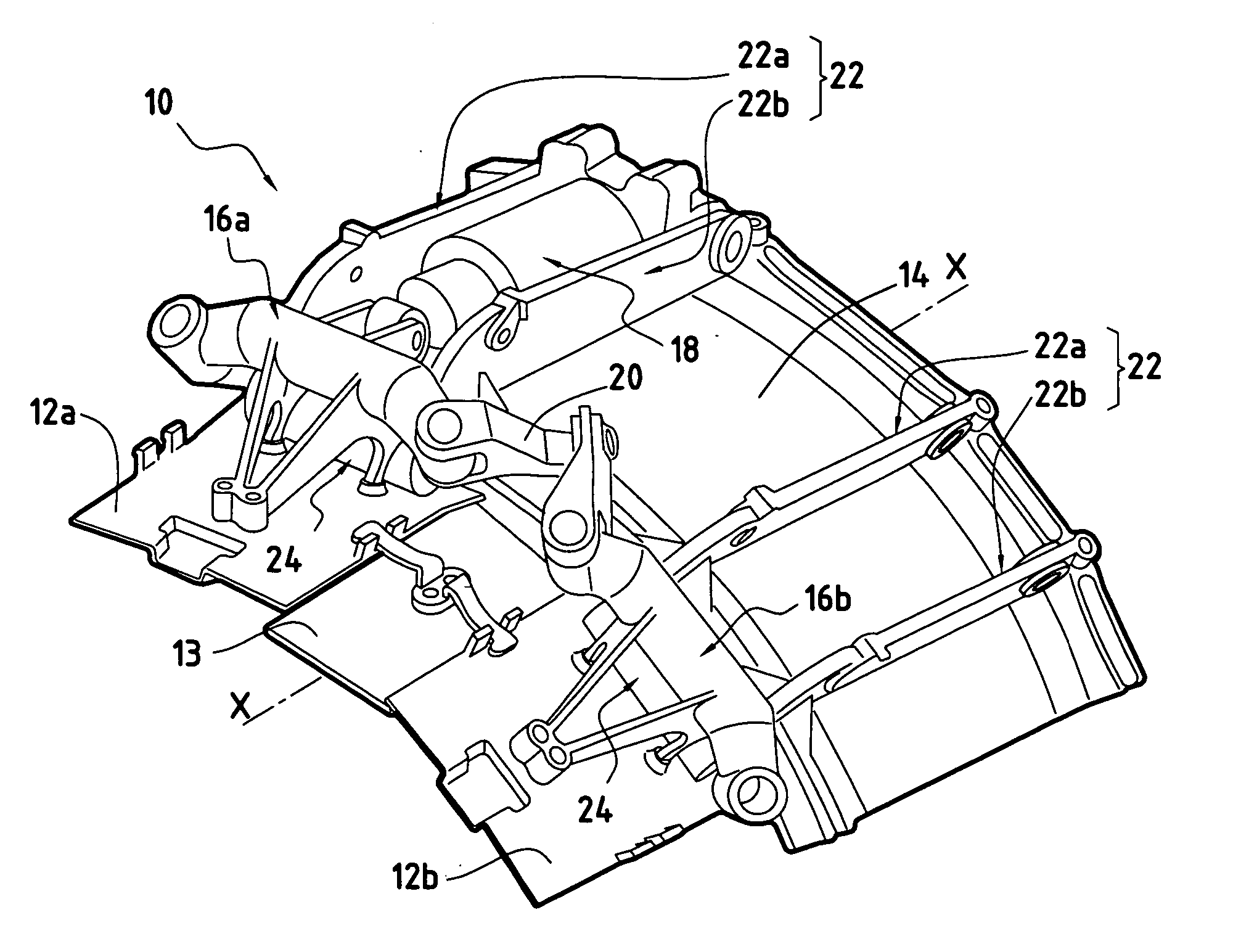
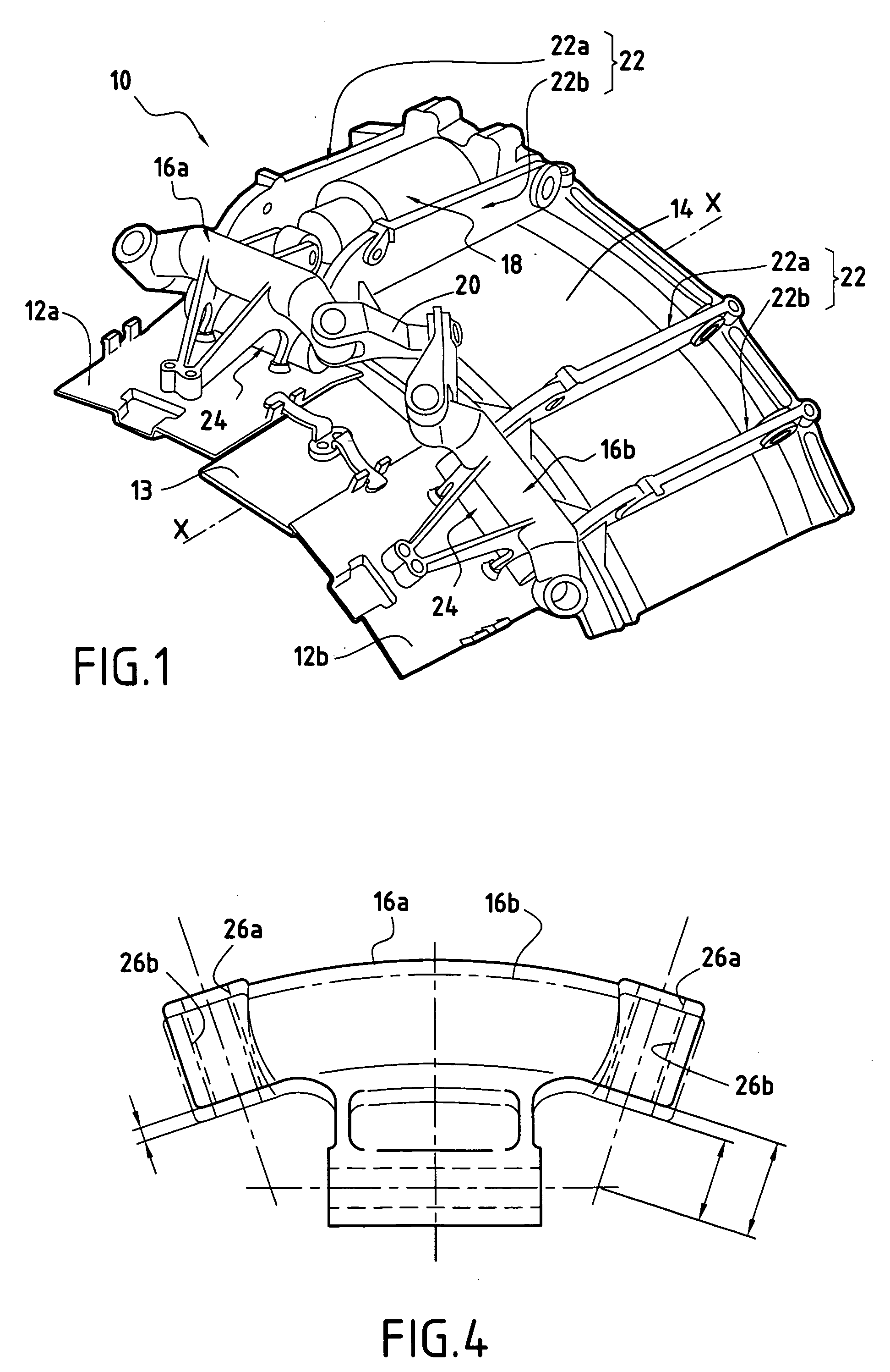
[0018]FIG. 1 shows a portion of a variable-section turbomachine nozzle 10 of the invention.

[0019] The nozzle 10 of axis X-X comprises in particular a plurality of controlled moving flaps 12a and 12b and follower moving flaps 13 which are mounted on a downstream end of an annular casing 14 of the turbomachine that is centered on the axis X-X. The controlled flaps 12a and 12b and the follower flaps 13 thus form a ring.

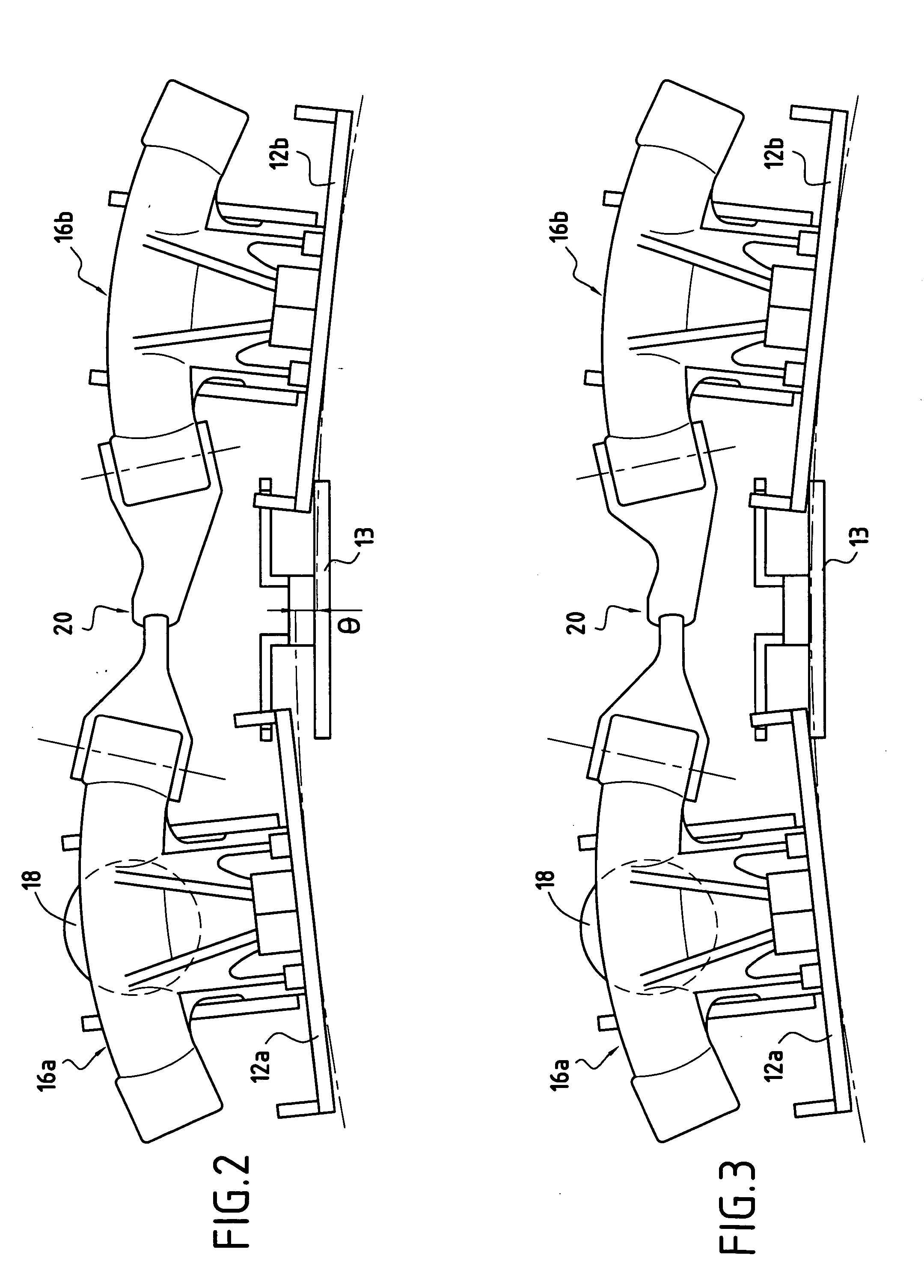
[0020] The controlled moving flaps 12a, 12b are actuated directly by a control system so as to change the profile of the primary stream from the turbomachine (i.e. its exhaust section).

[0021] The control system for controlled flaps 12a, 12b comprises control levers 16a, 16b each associated with a respective moving flap 12a, 12b, and at least one actuator 18 for actuating the control levers. Each control lever 16a, 16b is secured to the moving flap 12a, 12b that it controls.

[0022] More particularly, in the example of FIG. 1, a single actuator 18 serves to actuate two ...


PUM


Abstract

A variable-section turbomachine nozzle comprises a plurality of moving flaps, and a moving flap control system comprising control levers each associated with a respective moving flap, the control levers comprising both controlled levers that are actuated directly by actuators, and follower levers that are actuated by the controlled levers via transmission links. When the nozzle is at rest, the flaps associated with the follower levers present a radial offset relative to the flaps associated with the controlled levers.

Description

BACKGROUND OF THE INVENTION [0001] The present invention relates to the general field of variable-section nozzles for turbomachines, and more particularly it relates to nozzles made up of a plurality of moving flaps forming a ring. [0002] In a conventional architecture for a turbomachine nozzle of variable section, the nozzle is constituted in particular by a ring of moving flaps that are mounted to extend an annular casing of the turbomachine. [0003] The moving flaps are actuated by a control system so as to modify the profile of the primary stream of the turbomachine (i.e. its exhaust section). Depending on the intended configuration, the control system comprises one or more control actuators associated with a more or less complex linkage, e.g. making use of control levers and swivelling-fork connections. [0004] The present invention relates more precisely to a variable-section nozzle of the type in which the control levers for the moving flaps comprise both controlled levers that...

Claims


Application Information

Patent Timeline
Patent Type & Authority Applications(United States)
IPC IPC(8): F02K1/12
CPCF02K1/1207
Inventor DAKOWSKI, MATHIEULAPERGUE, GUYLUNEL, ROMAINSEVI, GUILLAUME
Owner SN DETUDE & DE CONSTR DE MOTEURS DAVIATION S N E C M A
Why Eureka
Try Eureka