Continuous transfer type freezer

a technology of transfer type and freezer, which is applied in the direction of domestic cooling apparatus, rolling carts, lighting and heating apparatus, etc., can solve the problems of reducing cooling efficiency, unable to use holes, and lack of directionality of jet flows, so as to increase heat transfer coefficient and high heat transfer

Active Publication Date: 2006-05-04
MAYEKAWA MFG CO LTD
View PDF15 Cites 8 Cited by
  • Summary
  • Abstract
  • Description
  • Claims
  • Application Information

AI Technical Summary

Benefits of technology

[0011] The present invention is made in light of the problems mentioned above. An object of the invention is to achieve high heat transfer between the chilled air and the surface of the article to be cooled on a conveyor belt by spouting chilled air from slit nozzles provided above and under a conveyor belt in the form of air jets toward both surfaces of the conveyor belt in the direction perpendicular to the surfaces of the belt, whereby thin chilled air stream layer is formed on the surface of the article by virtue of Coanda effect, resulting in increased heat transfer coefficient between the chilled air and the surface of the article.
[0012] The second object of the invention is to increase heat transfer coefficient between the chilled air and the surface of the article to increase cooling effect by allowing thin air stream layer to be formed along the surface of the article by virtue of Coanda effect even when the distance between the nozzle opening and the article is relatively large through rectifying the air flow in the nozzle and giving strong directionality to the air jetted from the nozzle.
[0013] The third object of the invention is to provide a structure with which the formation of passages for exhausting chilled air does not constitute a limiting factor of providing nozzles under the conveyor belt, for if the number of nozzles provided under the conveyor belt is limited as is in said prior art 1, cooling effect is decreased.

Problems solved by technology

Further, as air jet streams are formed by sacking air by the fan through the holes bored in the upper wall, the jet flows lack in directionality and tend to diffuse or proliferate.
Further, air exit openings are provided below the conveyor belt at certain intervals, so nozzles can not be provided where the exit openings are provided under the conveyor belt, resulting in decreased cooling efficiency.
Therefore, the conveyor belt must have holes and a conveyor belt not having holes can not be used.
Therefore, loading density of the articles transferred on the belt is limited, because there must be left on the belt space not occupied by the articles in order to allow the air introduced into the tunnel through the nozzles (holes) to flow downward through the holes of the conveyor belt.
Further, the space in which the conveyor belt passes through is narrow and inconvenient to clean.
Therefore, it is necessary to provide a number of cleaning nozzles, and the installation becomes complicated resulting in increased cost.

Method used


Image

  • Continuous transfer type freezer
  • Continuous transfer type freezer
  • Continuous transfer type freezer

Examples


first embodiment

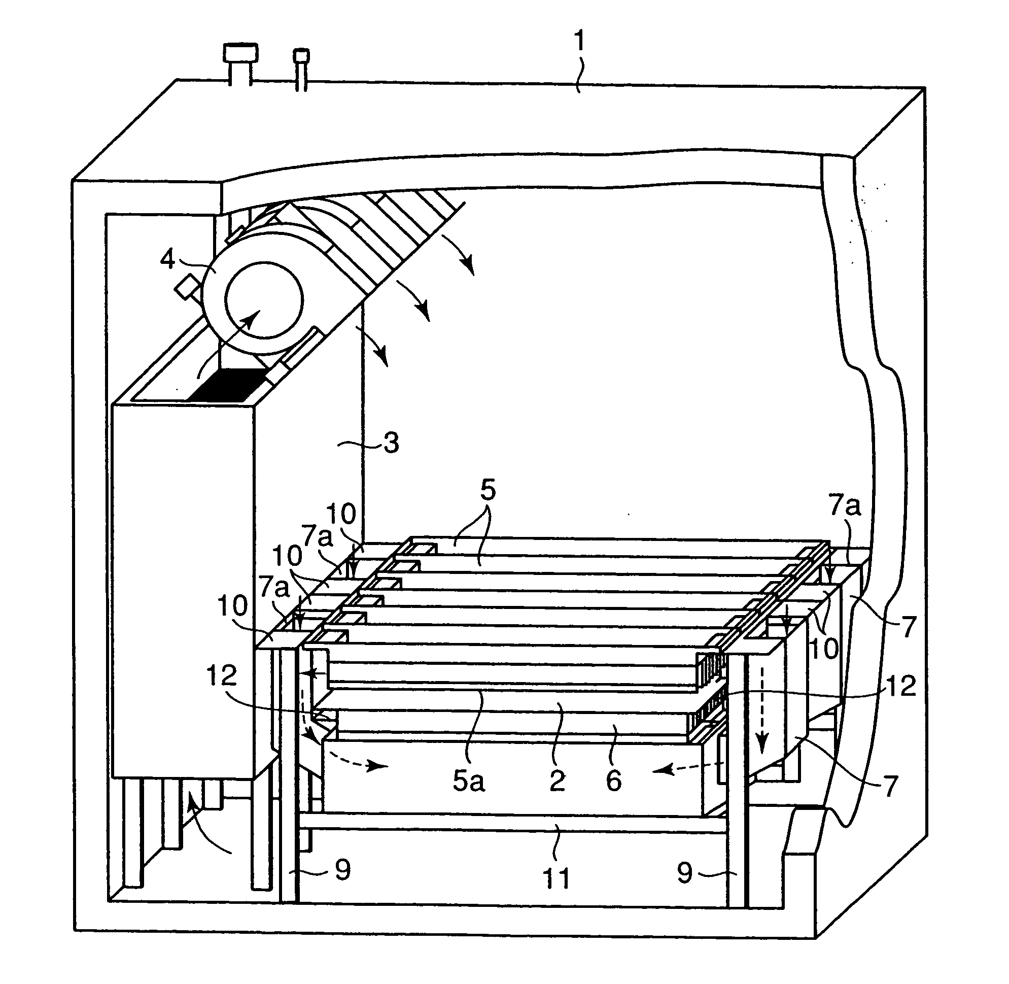
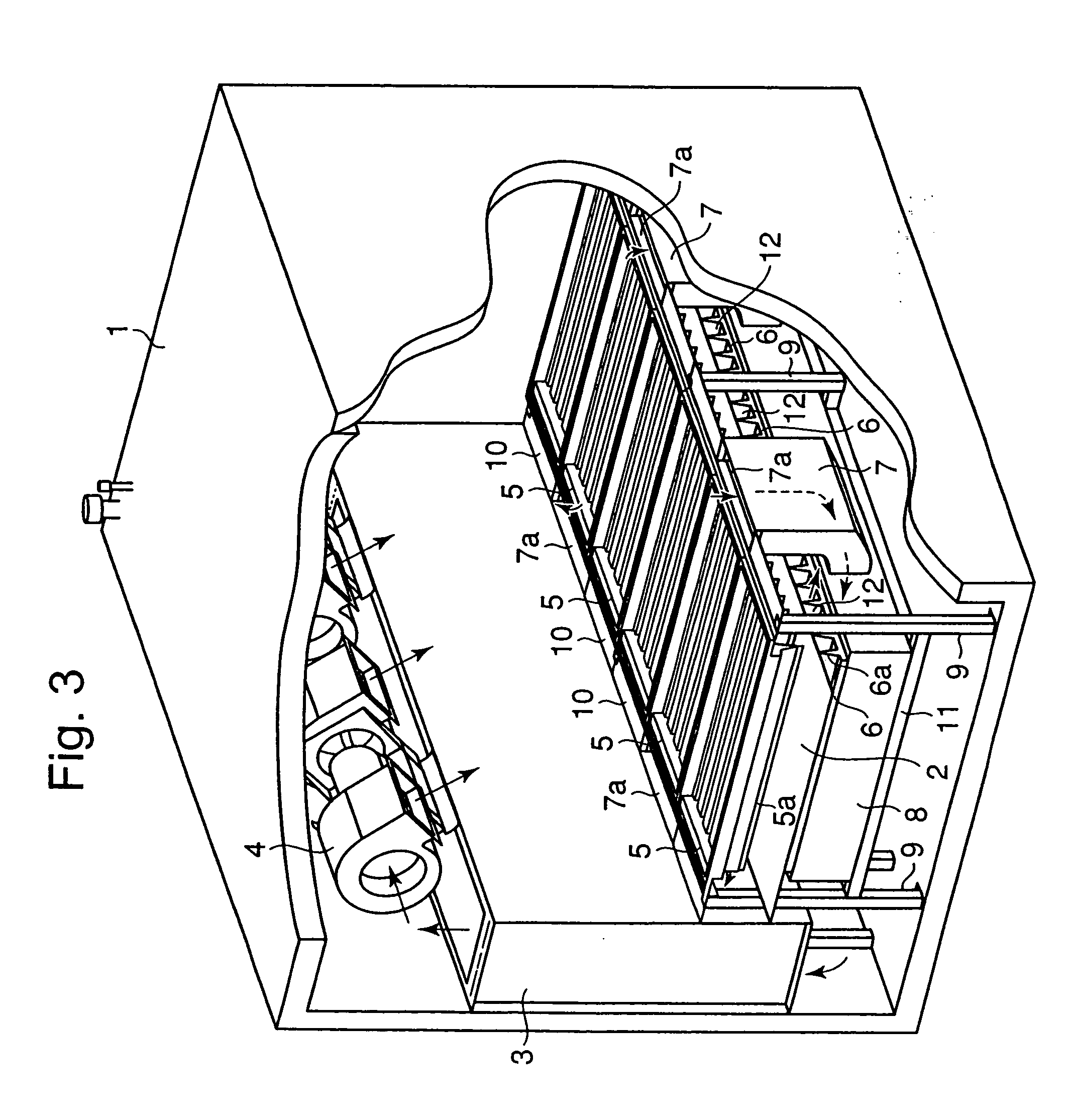
[0037] Referring to FIG. 3 and FIG. 4 showing the present invention, reference numeral 1 is a housing which is preferably composed of heat insulating walls. The housing is closed except an entrance opening and an exit opening not shown in the drawings for entrance and exit of a conveyor belt 2. Chilled air is circulated in the housing. Reference numeral 3 is a cooler and 4 are cooling fans to constitute a part of a chilled air cycle.

[0038] Reference numeral 5 are upper slit nozzle units located above the conveyor belt 2. Each of the units 5 is composed of a plurality of upper slit nozzle 5a. Reference numerals 9 are columnar supports for supporting the conveyor belt 2, upper slit nozzle units 5, etc. Reference numerals 10 are longitudinal frames attached to the columnar supports 9. A plurality of upper slit nozzle units 5 are placed on the longitudinal frames 10 to be capable of being uplifted. Reference numerals 6 are lower slit nozzle units located under the conveyor belt. Each of...

second embodiment

[0048]FIG. 6 is a partially enlarged side view schematically representing the present invention.

[0049] When there is difference between the pressure near the entrance opening and that near the exit opening of the housing, there occurs an air stream flowing from the opening side of higher pressure toward the opening side of lower pressure and the air may flow out from the housing or outside air may flow into the housing. When this occurs, chilled air leaks out of the housing and workers may be adversely affected or outside air intrudes into the housing and the cooler may be frosted resulting in decreased performance of the cooler. The second embodiment aims to solve this problem. Referring to FIG. 6, when chilled air stream flowing from the entrance opening not shown in the drawing toward exit opening 22 of the housing 21 as shown by an arrow in the drawing, leading end parts 23a of slit nozzles of an upper slit nozzle unit 23 located near the exit opening 22 of the housing 21 are sl...


PUM


Abstract

A continuous transfer type freezer for cooling or freezing articles such as foodstuffs transferred on a conveyor belt by spraying chilled air from slit nozzles on the articles is provided in which chilled air jets rectified to have long spray travel is produced, thin stream layer of chilled air is formed on the surface of the article to achieve increased heat transfer, and exhaust passages of the chilled air are formed such that they do not affect the cooling function. A plurality of slit nozzles 5a, 6a are apposed above and under the conveyor belt along the belt transfer direction, each of the nozzles 5a, 6a is shaped such that it has an angled and succeeding parallel entrance way so that the chilled air is rectified in the entrance ways and spout from the nozzle opening at large velocity, and exhaust passages 12 are formed between each of the slit nozzles such that the chilled air spouted from the nozzles flows toward both lateral end sides of the conveyor belt 2.

Description

CROSS REFERENCE TO RELATED APPLICATIONS [0001] This is a continuation of International Application PCT / JP2004 / 016464, with an international filing date of Oct. 29, 2004; this International Application was not published in English.TECHNICAL FIELD [0002] The present invention relates to a transfer type freezer capable of continuous cooling or continuous freezing; in which a chilled air jet is impinged on an article transferred on a conveyer belt, whereby a thin stream layer is formed on the surface of the article owing to Coanda effect resulting in higher cooling effect; in which exhaust passages are formed for guiding the air impinged on the article in both width directions of the belt; and in which apparatuses are located in a single space surrounded by the housing, whereby the chilled air can circulate in the housing more easily, its flow loss is reduced, and maintenance such as cleaning can be performed easily. BACKGROUND ART [0003] A method to cool, heat, or dry an article such a...

Claims


Application Information

Patent Timeline
Patent Type & Authority Applications(United States)
IPC IPC(8): F25D17/06F25D25/04F25D13/06
CPCF25D13/067F25D2317/0683
Inventor ISHIKURA, KOUARAI, TAKAHIROTANIYAMA, AKIRA
Owner MAYEKAWA MFG CO LTD
Why Eureka
Try Eureka