Directed Flow Nozzle Swirl Enhancer

a technology of swirl enhancer and flow nozzle, which is applied in the direction of machines/engines, mechanical equipment, transportation and packaging, etc., can solve the problems of reducing the efficiency of the engine, difficult to distribute thermal energy evenly throughout the part to be heated, and undesirable accumulation of ice on the aircraft engine, etc., to achieve the effect of improving the heat transfer coefficient of the component and improving the heat transfer through the leading portion of the aircraft engin

Active Publication Date: 2017-11-02
GENERAL ELECTRIC CO
View PDF5 Cites 0 Cited by
  • Summary
  • Abstract
  • Description
  • Claims
  • Application Information

AI Technical Summary

Benefits of technology

[0003]This need is addressed by a structure within the component to be heated that is configured to increase the heat transfer coefficient within the component.
[0004]According to one aspect of the present invention there is provided an apparatus for improving heat transfer through a leading portion of an aircraft engine. The apparatus includes an annular channel that is defined by the leading portion. A source for gas that is fluidly connected to the channel and a narrow region that is defined within the annular channel.

Problems solved by technology

The accretion or buildup of ice on an aircraft engine is undesirable.
One problem with these methods is that distributing thermal energy evenly throughout the part to be heated is difficult.
As a result, either ice buildup happens on portions of the component that are not heated sufficiently or additional fluid flow from another part of the engine is needed to provide the required thermal load.
Such an increase in fluid flow reduces efficiency of the engine.

Method used


Image

  • Directed Flow Nozzle Swirl Enhancer
  • Directed Flow Nozzle Swirl Enhancer
  • Directed Flow Nozzle Swirl Enhancer

Examples


Embodiment Construction

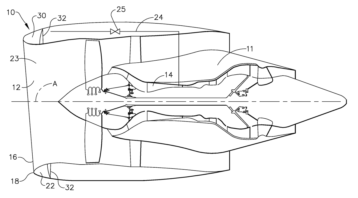
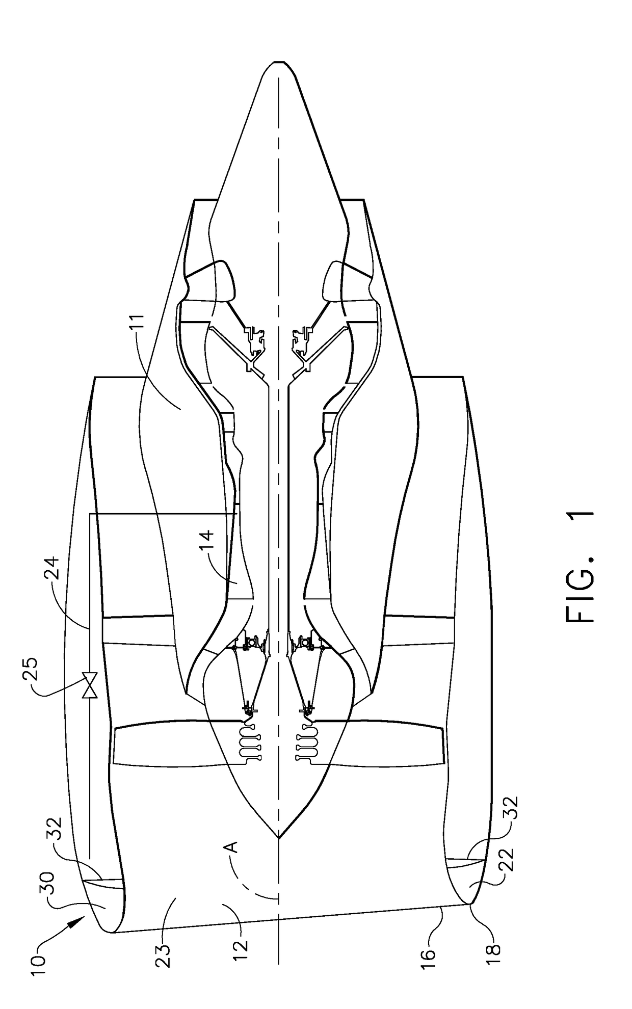
[0010]Referring to the drawings wherein identical reference numerals denote the same elements throughout the various views, FIG. 1 shows a partially cutaway view of a nacelle 10 that defines the leading portion of an engine 11. The nacelle 10 has a D-duct 30 defined therein. The D-duct 30 is configured to increase the speed of gas introduced into it such that the gas can circulate around the entire circumference of the D-duct 30.

[0011]The nacelle 10 of the engine 11 has a wall 16 that has an inner surface 22 and an outer surface 23. The outer surface 23 of the wall 16 defines an inner lip 12 and an outer lip 18. The inner surface 22 defines the D-duct 30 in conjunction with a D-duct-floor 32.

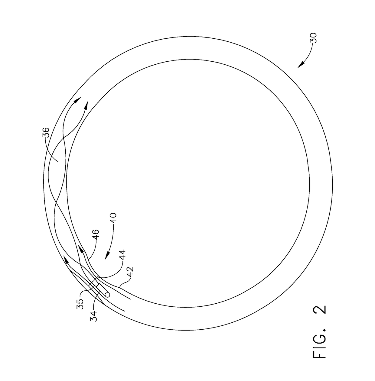
[0012]The D-duct 30 is an annular chamber defined by the inner surface 22 of the wall 16 that is positioned around an axis A of the engine 11. As shown, the D-duct 30 has a D-shaped cross-section. As shown in FIG. 2, a directional flow nozzle 34 extends into the D-duct 30. The directional flow n...


PUM


Abstract

An apparatus for improving heat transfer through a leading portion of an aircraft engine. The apparatus includes an annular channel that is defined by the leading portion. A source for gas that is fluidly connected to the channel and a narrow region that is defined within the annular channel.

Description

BACKGROUND OF THE INVENTION[0001]The present invention relates to heating components of an aircraft engine and more particularly to heating the leading edge of an aircraft engine.[0002]The accretion or buildup of ice on an aircraft engine is undesirable. In order to reduce ice buildup, it is known to introduce heated fluid from one part of an engine to the other components of the engine. One problem with these methods is that distributing thermal energy evenly throughout the part to be heated is difficult. As a result, either ice buildup happens on portions of the component that are not heated sufficiently or additional fluid flow from another part of the engine is needed to provide the required thermal load. Such an increase in fluid flow reduces efficiency of the engine. Accordingly, there is a need for an apparatus to more efficiently use fluid flow to heat an aircraft component.BRIEF DESCRIPTION OF THE INVENTION[0003]This need is addressed by a structure within the component to ...

Claims


Application Information

Patent Timeline
Patent Type & Authority Applications(United States)
IPC IPC(8): F02C7/047
CPCF02C7/047B64D15/04B64D2033/0233F05D2260/14F05D2260/601F05D2250/25
Inventor TIWARI, PRASHANTMUKHERJEE, SHILADITYAWIBERG, CLARK GEORGE
Owner GENERAL ELECTRIC CO
Why Eureka
Try Eureka