Method and apparatus for particle injection moulding

a particle and injection moulding technology, applied in the field of particle injection moulding, can solve problems such as defects in the region

Active Publication Date: 2018-01-18
ROLLS ROYCE PLC
View PDF14 Cites 0 Cited by
  • Summary
  • Abstract
  • Description
  • Claims
  • Application Information

AI Technical Summary

Benefits of technology

[0027]The direct temperature control of an internal feature forming element using a temperature control circuit in the element, allows a temperature controlling medium to be provided into an area of the ceramic core that would otherwise form a hot or cold spot relative to the overall die temperature during an injection moulding process. The arrangement allows for more complex ceramic cores to be manufactured with a reduction in surface defects on internal features of the cores. This permits an advantageous increase in the ceramic core complexity which can be used to provide gas turbine component designs with reduced cooling air requirements. A consequent increase in gas turbine efficiency and a related reduction in specific fuel consumption costs is expected to result when the die design is used for manufacture of ceramic cores for use in the investment casting of gas turbine components.
[0029]The micro-channels themselves are configured and arranged to improve the heat transfer behaviour with the aim of reducing the ceramic core surface defects. The micro-channels may be straight, spiral, contoured or follow a serpentine arrangement. The micro-channels may contain turbulators, pin fins or pedestal features that increase the cooling effectiveness. They may be coated in a substance that improves the heat transfer coefficient. They may follow a contour which creates a thinner wall closer to the ceramic core defect area, in order to increase the local rate of heat transfer but have a thicker wall elsewhere in order to provide structural rigidity to the internal feature forming element.

Problems solved by technology

Subsequently, this may lead to defects in that region which occur as the result of the ceramic core material adhering to the die as a consequence of the elevated local temperature.
A problem identified with use of the sacrificial insert results from it typically being made from a material that has a lower coefficient of thermal conductivity than the core die.

Method used


Image

  • Method and apparatus for particle injection moulding
  • Method and apparatus for particle injection moulding
  • Method and apparatus for particle injection moulding

Examples


Embodiment Construction

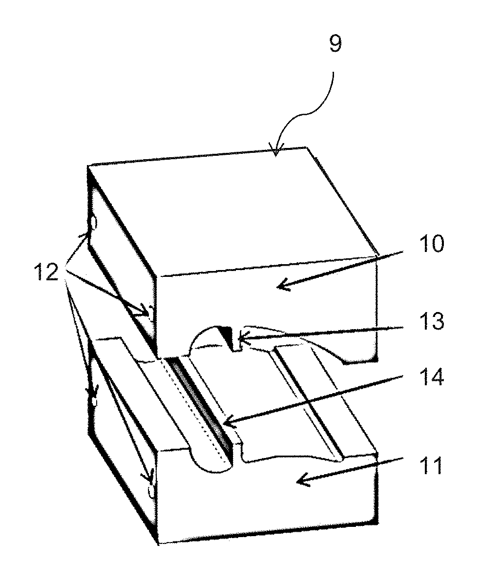
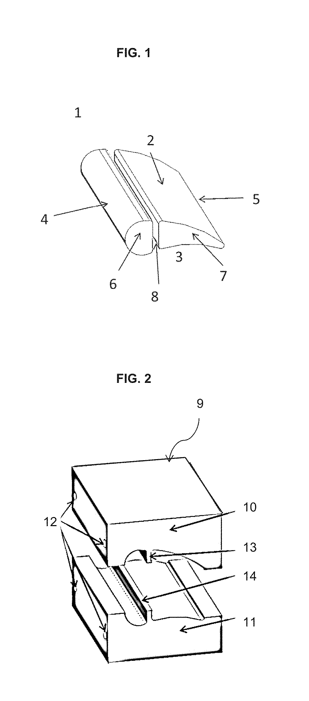
[0044]As can be seen from FIG. 5, elements forming the surfaces of an internal feature of the ceramic core are provided with a plurality of micro-channels that permit cooling by passing a cooling medium through the micro-channels. This serves to reduce the temperature of the surfaces of an internal feature during cooling of a ceramic core in the die. As can be seen, a pressure side ceramic core forming a pressure side die half 111, has a cooling fluid inlet 118, which supplies cooling fluid to a plurality of cooling micro-channels 119, contained within the internal feature forming element 114. The cooling fluid proceeds to flow through additional micro-channels 120, that are contained within a suction side core die half 110 within the internal ceramic core feature forming element 113. The cooling fluid proceeds to flow to an exit 121 within the suction side forming die half 110.

[0045]FIGS. 6 (a) and (b) shows an alternative embodiment of the invention wherein rather than from two pa...


PUM

PropertyMeasurementUnit
temperatureaaaaaaaaaa
latent heat energyaaaaaaaaaa
heat transfer coefficientaaaaaaaaaa

Abstract

A die for moulding a core by a PIM process, the core having at least one internal feature, the die including; a first die part defining a first portion of an outer surface of the core; a second die part defining a second portion of the outer surface of the core; and an internal feature forming element for defining the surface of an internal feature of the core; wherein the internal feature forming element incorporates a temperature control circuit.

Description

FIELD OF THE INVENTION[0001]The invention is concerned with particle injection moulding (PIM), for example (but without limitation), in the manufacture of ceramic cores for use in the investment casting of gas turbine blades. More particularly the invention is concerned with improved die apparatus which facilitates temperature control of internal features of a core moulded using the apparatus in a PIM process.BACKGROUND TO THE INVENTION[0002]Investment casting is an evolution of the lost-wax process whereby a component of the size and shape required in metal is manufactured using wax injection moulding. The moulded wax pattern is then dipped in ceramic slurry to create a shell; the wax is then removed and the ceramic shell fired to harden it. The resultant shell has open cavities into which molten metal can be poured to produce a metal component of the required shape and size. For example (but without limitation) the process is known to be used in the manufacture of turbine blades f...

Claims


Application Information

Patent Timeline
Patent Type & Authority Applications(United States)
IPC IPC(8): B22C9/10B28B7/42B28B1/24
CPCB22C9/10B28B7/42B28B1/24B22C7/06B29C33/0083B29C33/02B29C33/04B29C2033/042
Inventor CENDROWICZ, ALEKSANDER M.
Owner ROLLS ROYCE PLC
Why Eureka
Try Eureka