
Fluid Vortex Energy Transfer System

a technology of energy transfer system and fluid vortex, which is applied in the direction of geothermal energy generation, lighting and heating apparatus, and collectors with underground water as fluid, can solve the problems of expensive and slow installation, and achieve the effects of increasing the amount of heating/cooling, and speeding up the pump

Inactive Publication Date: 2009-02-12
COURTRIGHT GEOFFREY B
View PDF3 Cites 2 Cited by
  • Summary
  • Abstract
  • Description
  • Claims
  • Application Information

AI Technical Summary

Benefits of technology

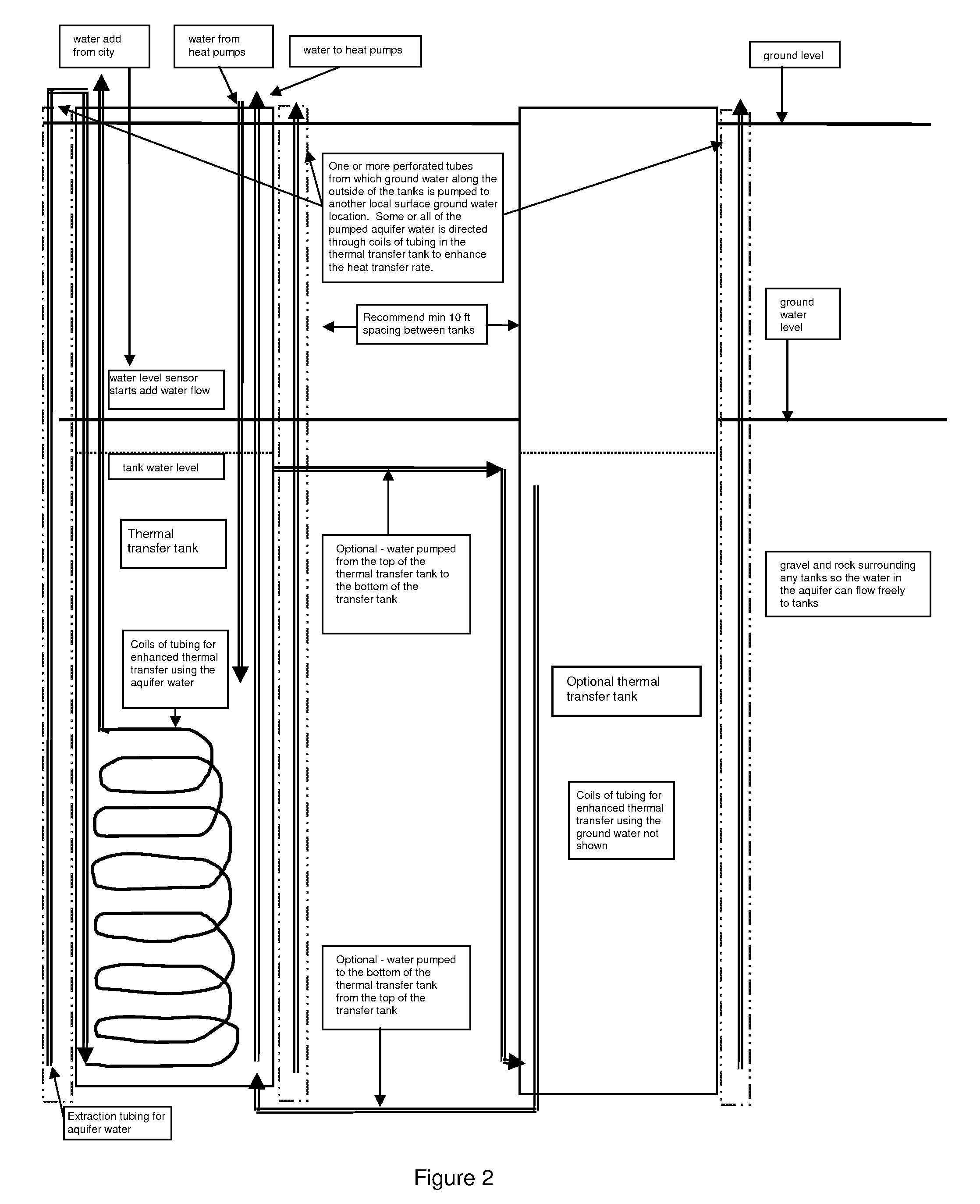
[0013]The vortex flow of fluid from the heat pump(s) moves over temperature transfer coils located within the tank. The coils are formed from compounds that allow the transfer of heat into or out of the coil, such as but not limited to copper, cupronickel, titanium, polyethylene, etc. In an embodiment, the coils are made from a material having less metal than that used in a typical heat exchanger, or from a non-metal material. As such, the coils are much less costly and much less affected by corrosion or erosion so to deliver a much longer product life. In an embodiment, the coils form a spiral at a point starting near the bottom of the tank. In an embodiment, the coil is a flat spiral. The space between the spirals is sufficient to allow the tank fluid to circulate between the spirals. The coil is situated in the tank such that the vortex of the tank fluid is easily created. In an embodiment, the coil is about 1″ from the wall of the tank. The coils are of sufficient length and made of the appropriate material for the specific environment and tank fluid source characteristics and to meet the heating and cooling tonnage required. In an embodiment, the coil is a tube. In an embodiment, the coil has squared sides. In an embodiment, the coil is any shape and in any form such that the fluid in the coil flows in a direction against the flow of the tank fluid. In an embodiment, the coil is an about 1000 foot long, about ⅜″ diameter polyethylene tube.
[0015]To increase the amount of heating / cooling provided by the system, more coils and or additional coils and or faster pumps are added. The tank may be connected to additional tanks serving similar functions to increase the amount of heating / cooling.
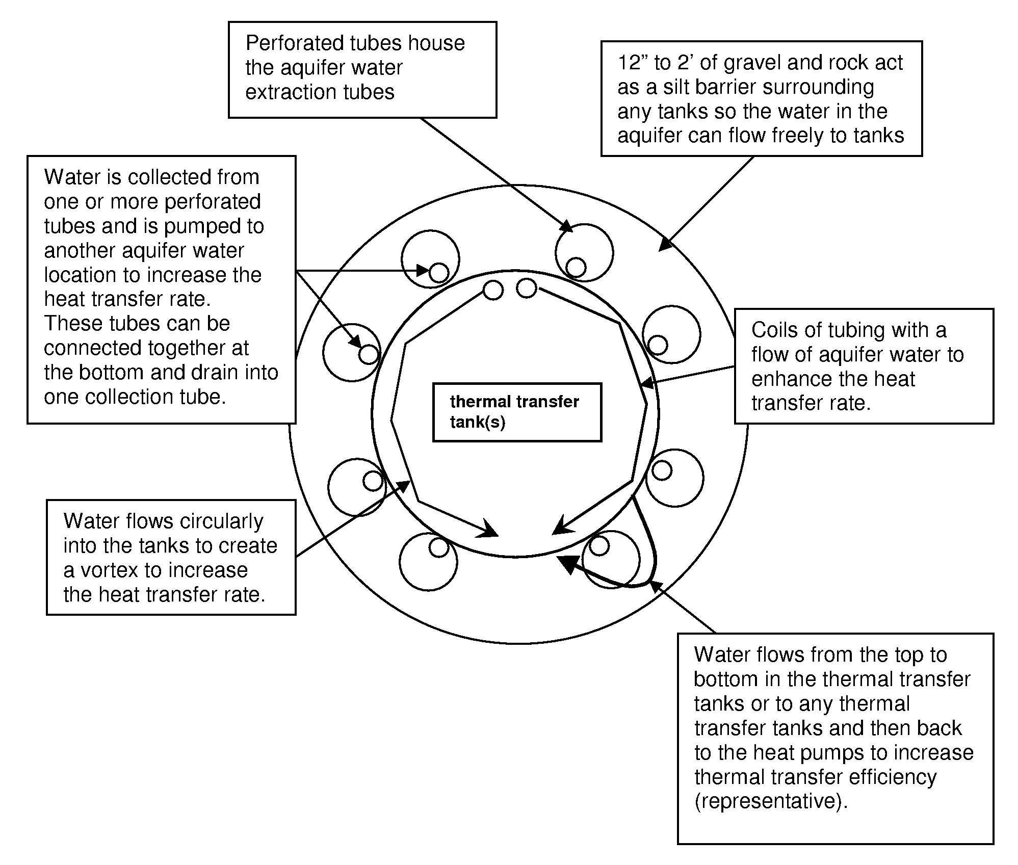
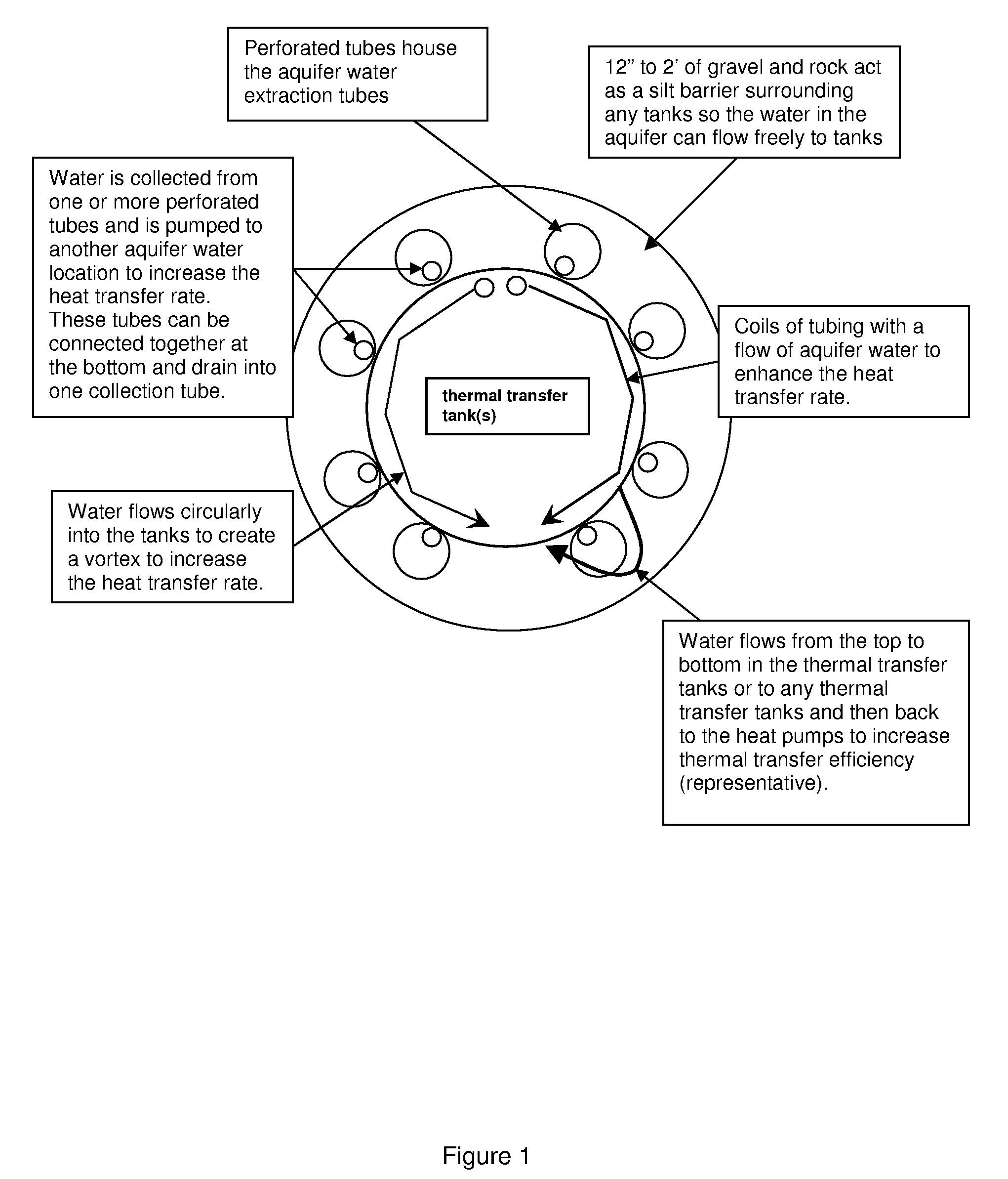
[0016]The vortex flow of fluid in the tank creates a forced convection with immersion for a much higher heat transfer coefficient. In an embodiment, the walls of the tank are fabricated from steel. In an embodiment, the outside of the tank is in contact with a silt barrier to allow the free flow of water against the outside of the tank. In an embodiment, the silt barrier or gravel or rock. Use of steel walls in direct contact with a ground water aquifer and constantly moving tank liquid on the inside of the tank(s) also increases the heat transfer coefficient. In an embodiment, the tank is a cylinder shape. In an embodiment, the tank is wider than it is tall, in an embodiment, the tank is taller than it is wide. In an embodiment, the inner tank wall comprises structures that assist in circulating the fluid, such as a manifold, a fin, a rudder, and the like.

Problems solved by technology

While geothermal systems transfer heat to and from the ground efficiently with minimal use of electricity and do not use fossil fuels, they are expensive and slow to install.

Method used


Image

  • Fluid Vortex Energy Transfer System
  • Fluid Vortex Energy Transfer System
  • Fluid Vortex Energy Transfer System

Examples


example

Heat Transfer in a Heat Exchange

[0065]A single plate exchanger with media A transfers heat to media B. The wall thickness is 0.1 mm and the material is polypropylene PP, aluminum or stainless steel. Media A and B are air with a convection heat transfer coefficient of hair=50 W / m2K. The overall heat transfer coefficient U per unit area can be expressed as:

U=1 / (1 / hA+dxw / k+1 / hB)   (1b)

[0066]Using the values from above the overall heat transfer coefficient can be calculated to:[0067]Polypropylene PP: U=24.5 W / m2K[0068]Steel: U=25.0 W / m2K[0069]Aluminum: U=25.0 W / m2K

[0070]Cooling Mode and Heat Flux

[0071]Heat flux for various cooling modes

[0072]The table below can be used to indicate the maximum heat flux for various cooling modes.

Heat FluxCooling Mode(kW / m2)Free Convection Air0.5Forced Convection Air5Free Convection Immersion10Forced Convection Immersion500Forced Convection Boiling1000Impingement Air10Jet Immersion, single phase400Jet Immersion, boiling900[0073]1 Btu / ft2 h=3.1525 W / m2

[00...


PUM


Abstract

A fluid energy transfer system comprising at least one coil containing a fluid pumped in a first flow direction. The fluid comes from a source and returns to the same source. The coil is enclosed within a tank. The tank contains a tank fluid. The tank fluid is pumped into the tank in a closed system from at least one heat pump. The tank fluid is circulated from the heat pump into the tank through at least one jet located along a wall of the tank. The tank fluid moves in a direction starting from a first end of the tank and exiting at a second end of the tank in an flow direction opposite that of the coil fluid. The circulation of the tank fluid creates a vortex that creates an increase in the heat transfer coefficient by forced convection in immersion of the tank fluid over the coil.

Description

CROSS-REFERENCE TO RELATED APPLICATIONS[0001]This application claims priority provisional application Ser. No. 60954352 filed Aug. 7, 2008.FIELD OF THE INVENTION[0002]The present invention relates generally to thermal energy transfer and specifically to dual fluid heating / cooling systems.BACKGROUND OF THE INVENTION[0003]Geothermal systems use the energy below the Earth's surface to transfer thermal energy. Below the approximately 48 inch frost line in the north, a temperature of approximately 48° F. is maintained year round in rock, aquifers and dirt. As the average above ground temperatures rise, so does the year round 48 inch below subsurface temperature to approximately 76° F. in southern Florida. A geothermal system transfers energy to or from a fluid in the geothermal system based on a difference in temperature of the surrounding earth.[0004]Geothermal systems are typically comprised of a closed tube, a pump, and a heat pump. The pump moves a fluid through the tube, where the f...

Claims


Application Information

Patent Timeline
Patent Type & Authority Applications(United States)
IPC IPC(8): F28D15/00
CPCF24J3/085Y02E10/14F28F13/06F28D15/00F24T10/20Y02E10/10
Inventor COURTRIGHT, GEOFFREY B.
Owner COURTRIGHT GEOFFREY B
Learn More