

Enhanced efficiency endothermic reactor for syngas production with flexible heat recovery to meet low export steam generation
a technology of endothermic reactor and syngas, which is applied in the direction of chemical/physical/physical-chemical stationary reactor, chemical apparatus and processes, chemical/physical/physical-chemical processes, etc., can solve the problems of differential thermal expansion, sleeve, inner and outer tubes, etc., to avoid flame impingement, increase the overall heat transfer coefficient, and less complex
- Summary
- Abstract
- Description
- Claims
- Application Information
AI Technical Summary
Benefits of technology
Problems solved by technology
Method used
Image

Examples
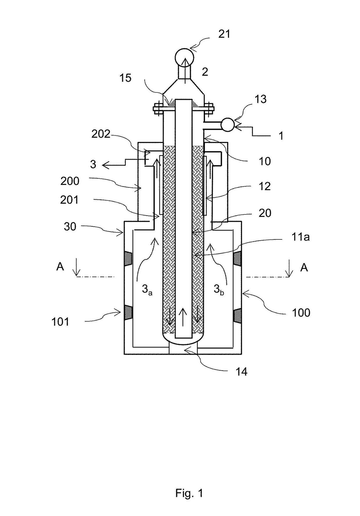
first embodiment
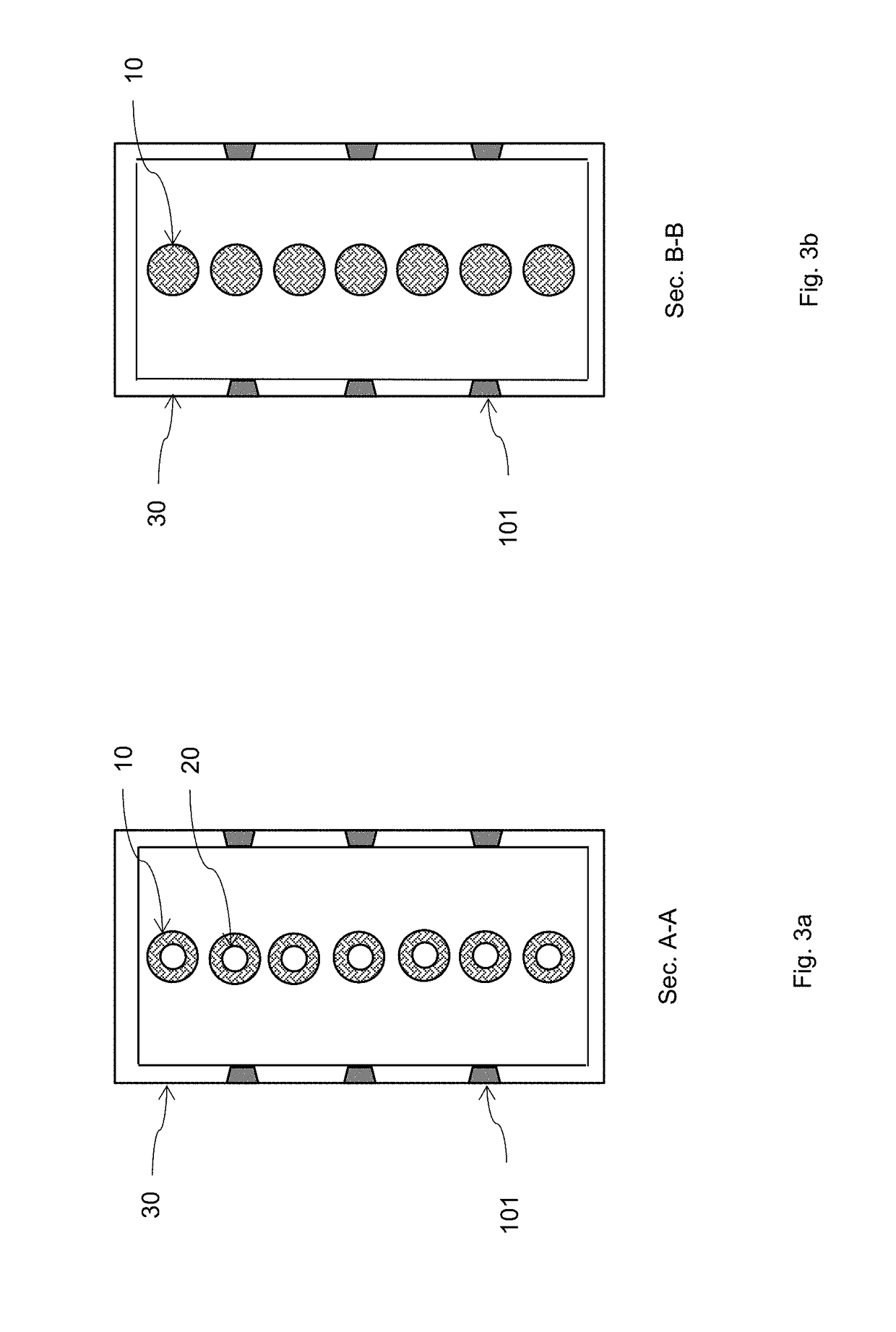
[0028]Such a flexible heat recovery is realized by means of two different embodiments of the same apparatus. Heat recovery from the flue gases is performed through the outer surface of the catalytic vessels in both embodiments (see FIG. 1,2), throughout a convective chamber surrounding a top portion of the catalytic vessels wherein the outer surface is equipped with an extended surface (either fins or studs). An additional heat recovery from the product syngas may be realized by means of an inner tube (in the first embodiment) located inside each catalyst vessel, wherein the hot syngas flows upward in counter-current with the reacting gas in the annular zone. In such a way the endothermic reactions are sustained by the product gas for a significant portion of the heat duty (10%÷30%).
[0029]The two different embodiments are specifically designed to obtain a maximum fuel efficiency (>70%) and zero export steam production (first embodiment), or else a lower fuel efficiency (60-70%) with...
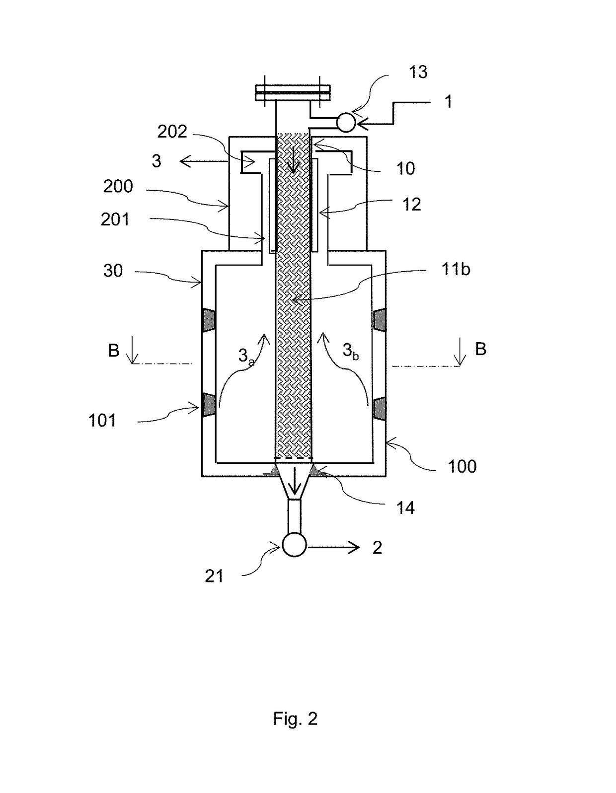
second embodiment
[0033]The presence of an enhanced catalytic device improves the process performance and reliability also in the ‘once through’ configuration of the catalytic vessels in the second embodiment, since in this case it avoids the formation of fine catalyst particles and dusts that can accumulate on the bottom leading with time to high pressure drops, and also in this case it increases the heat transfer coefficient with consequent decrease of the maximum skin temperatures.
[0034]The here proposed invention, as above outlined, realizes, through two different embodiments, a flexible and enhanced heat recovery, permitting to balance the request of export steam in one single equipment, without the need of installing a pre-reforming section and / or a convective reformer downstream the main reformer, in such a way that it overcomes specific issues of the prior art technology and represents a step ahead toward a more efficient, simple and reliable process.
[0035]The apparatus according to the inven...
PUM
 Abstract
Description
Claims
Application Information